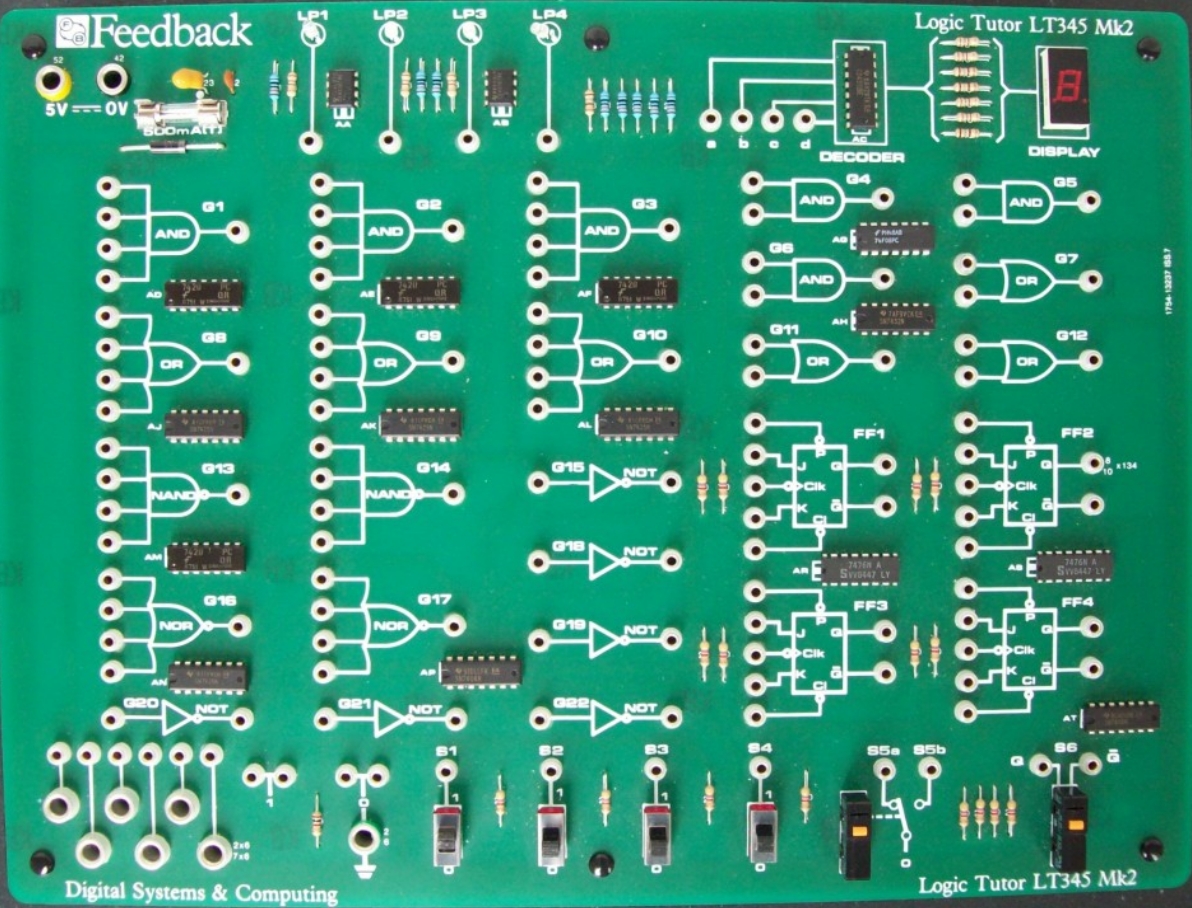
What do you do with a box of 35 solenoids? Or more precisely how can they be used to teach Boolean logic. My first thoughts were to build a safe, using the solenoid as the locking mechanism controlled via a digital switch pad, but that idea seemed to lack something. Thoughts then turned to building a better mouse trap, or as this is for a computer science module, building a better bug trap i.e. debugging :). The logic circuits used to control the solenoid are implemented on a Logic Tutor proto-type board, as shown in figure 1.
Figure 1 : Logic tutor board
Using logic gates and flip-flops a series of ever more elaborate bug traps are developed in the laboratory sessions. The bug trap controlled by these circuits is shown in figure 2, the bug in figure 3. The bug trap consists of two main parts: the top solenoid stamper and a bottom light dependent resistor (LDR) sensor pad to detect the bug's presence (the bottom of the bug is painted black i.e. light no bug, dark bug present).
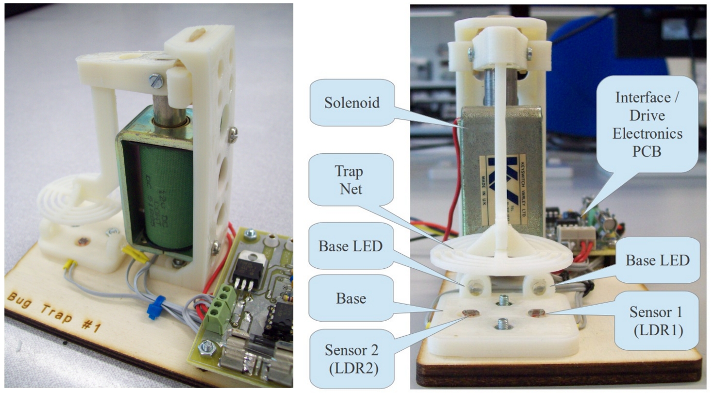
Figure 2 : Bug trap
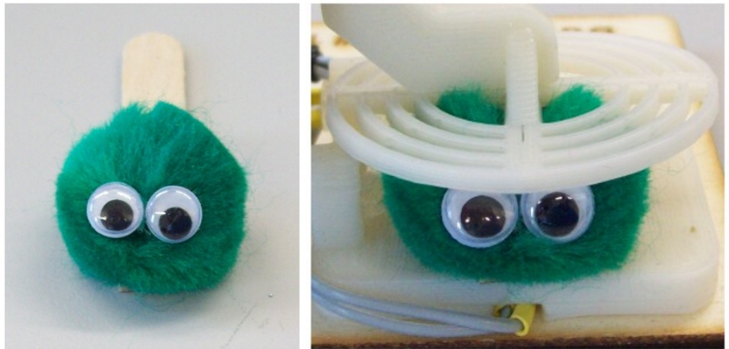
Figure 3 : Bug
To interface the solenoid and LDRs to the Logic Tutor board the circuit in figure 4 is used. LDRs are not shown in the circuit diagram, but are connect to TB1. This forms two potential dividers, the voltage of which can be adjusted by the variable resistors shown. These analogue voltages are then 'squared' using 7414 inverters i.e. a very dodgy 1bit ADC, outputting a logic 0 when the bug is not present and a logic 1 when it covers the LDR. The state of each LDR is displayed on an LED. The solenoid is controlled by a simple common source driver, with a flywheel diode and RC snubber for protection. In addition to these circuits there is a very low frequency 0.5Hz - 1Hz oscillator implemented from a 555 astable multi-vibrator (needs to be slow so that you can measure the period using a LED). Top and bottom PCB art work is shown in figures 5 - 7, Eagle (Link ) files are available here: schematic (Link ), PCB layout (Link )
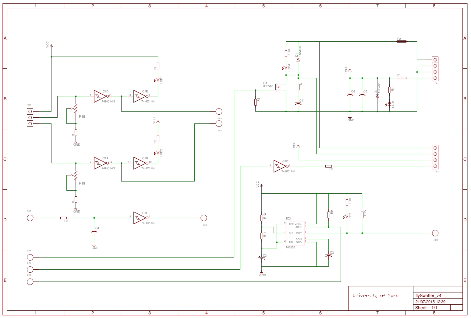
Figure 4 : Interface circuit
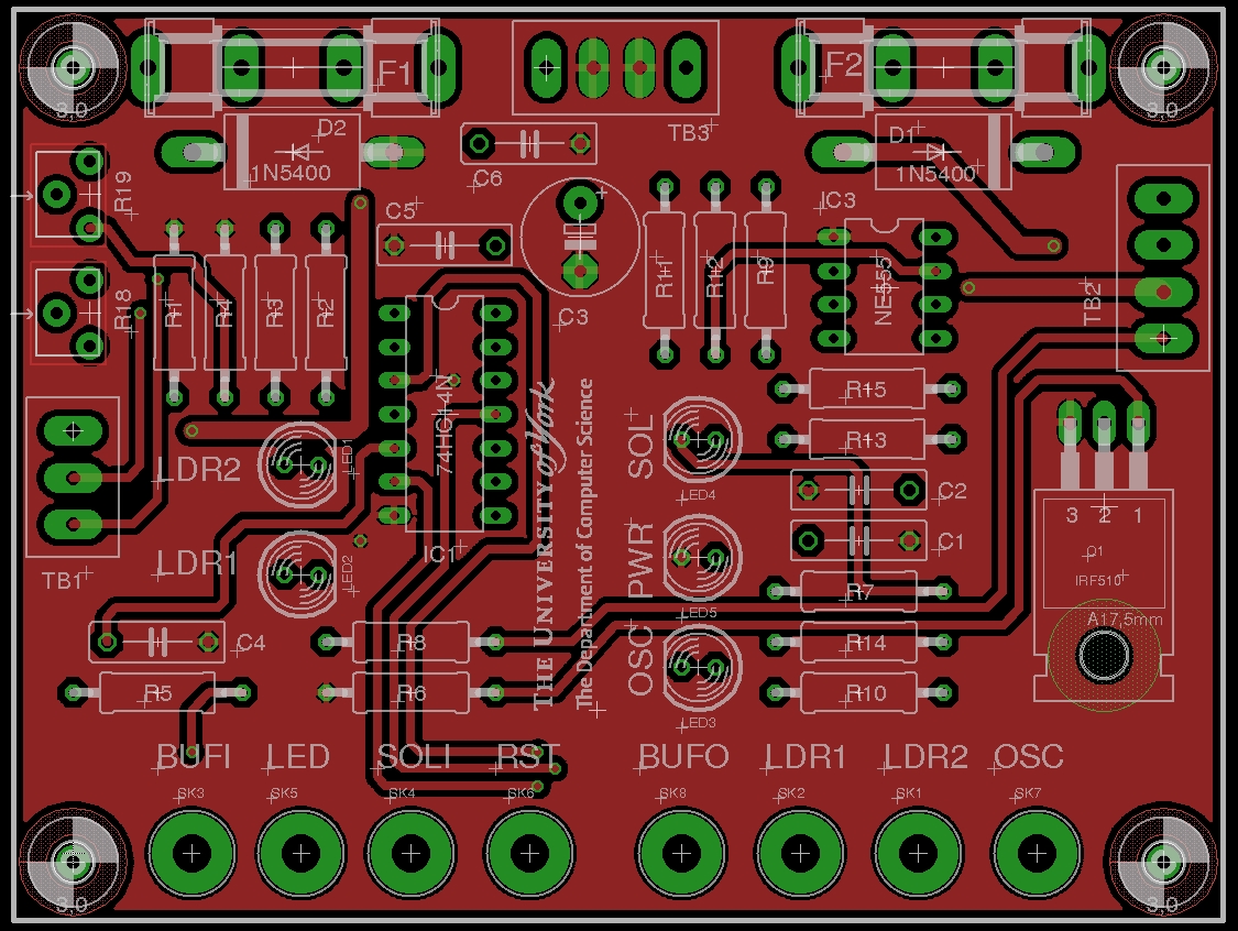
Figure 5 : Interface PCB top layer
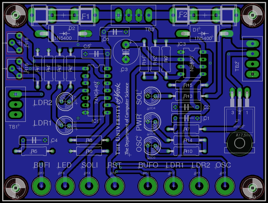
Figure 6 : Interface PCB bottom layer
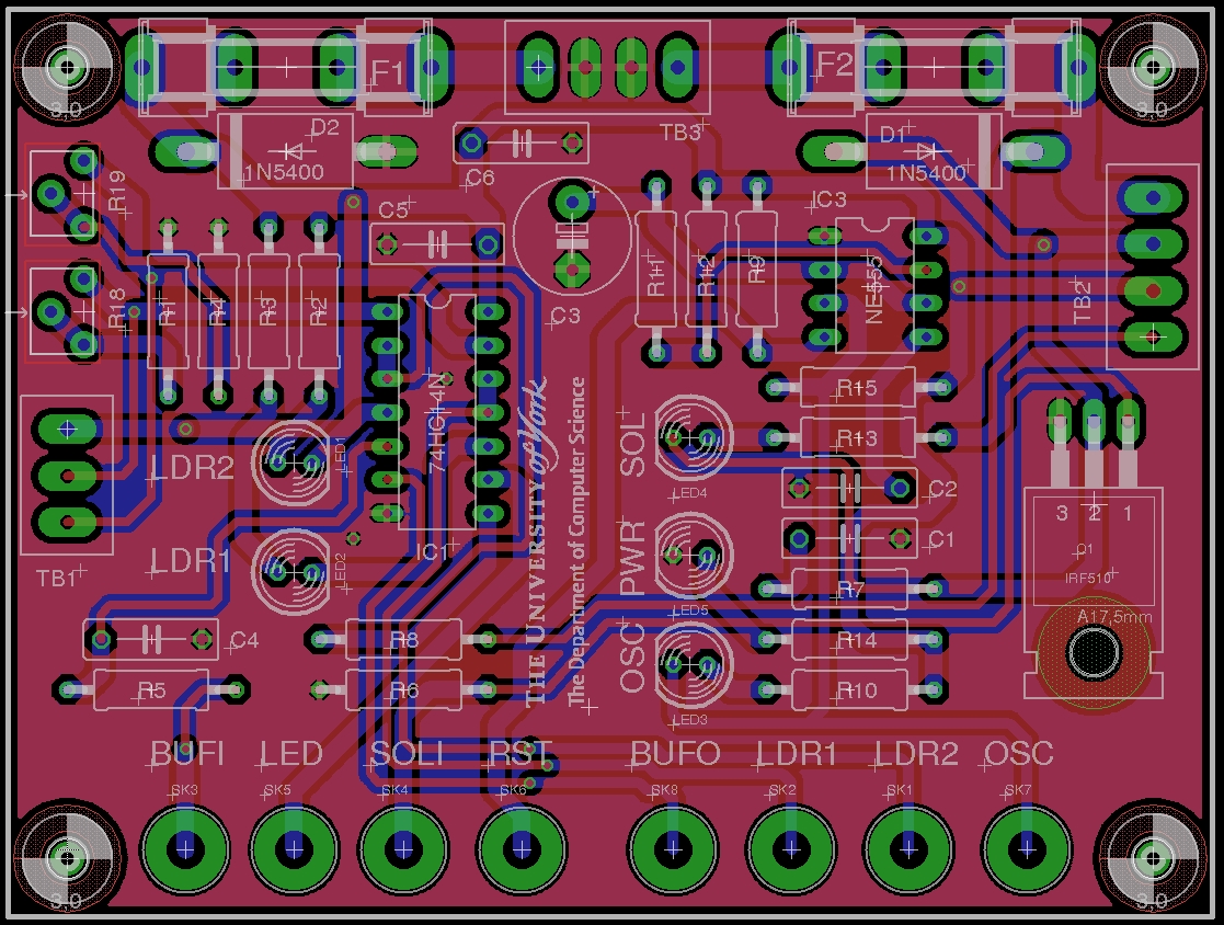
Figure 7 : Interface PCB all layers
The plastic components shown in figure 8 are 3D printed in ABS and mounted using M3 bolts onto a 5mm plywood base. To raise the stamper into its open position a small rubber band is looped around the frame and the top arm. This 3D model can be downloaded from: openscad (Link ), STL (Link ), other versions are also available in this directory. Note, rubber bands are a cheap and cheerful solution, but do perish over time, if i was doing this again i would go for a metal spring.
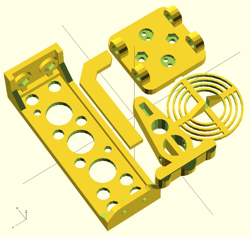
Figure 8 : Plastic components
This hardware is used in two laboratory sessions: basic logic gates and sequential logic circuits. The scenario is that the University is overrun with cockroaches, students are required to design an automatic cockroach trap. To allow the trap to work at night i.e. without human assistance, the trap's LEDs and LDR sensors (on base) need to be incorporated into a set of control rules. The trap is controlled using three switches:
The trap's behaviour can be defined as:
IF [MANUAL AND (ENABLE AND FIRE)]
    OR
   [AUTOMATIC AND (SENSOR1 OR SENSOR2)]
THEN
	CLOSE TRAP
ELSE
	OPEN TRAP

IF AUTOMATIC
THEN
	TURN ON BASE LEDS
ELSE
	TURN OFF BASE LEDS
Identifying the logical relationships between these switches (signals) the following circuit can be constructed.
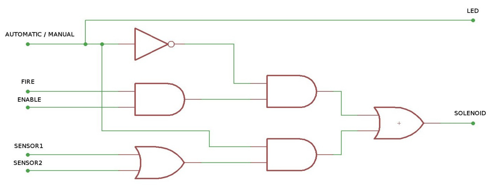
Figure 9 : Control circuit 1
Later, a new breed of heavy weight cockroaches are discovered. These are longer and more powerful than your typical bug. If caught these cockroaches can push their way through the trap i.e. they can not walk backwards. Therefore, the circuit needs to be modified to implement the following additional rules:
The aim of this update is to introduce the XOR logic gate i.e. a gate that only produces a logic 1 on its output when there are an odd number of logic 1s on its inputs. To produce the stamping behaviour the bug trap's 1Hz OSC square wave output signal can be used. The trap's new behaviour can be defined as:
IF [MANUAL AND (ENABLE AND FIRE)]
   OR
   [AUTOMATIC AND (SENSOR1 XOR SENSOR2)]
THEN
	CLOSE TRAP
ELSIF [AUTOMATIC AND (SENSOR1 AND SENSOR2)]
THEN
	STAMP ON BUG
ELSE
	OPEN TRAP

IF AUTOMATIC
THEN
	TURN ON BASE LEDS
ELSE
	TURN OFF BASE LEDS
Identifying the logical relationships between these switches and signals the following circuit can be constructed.
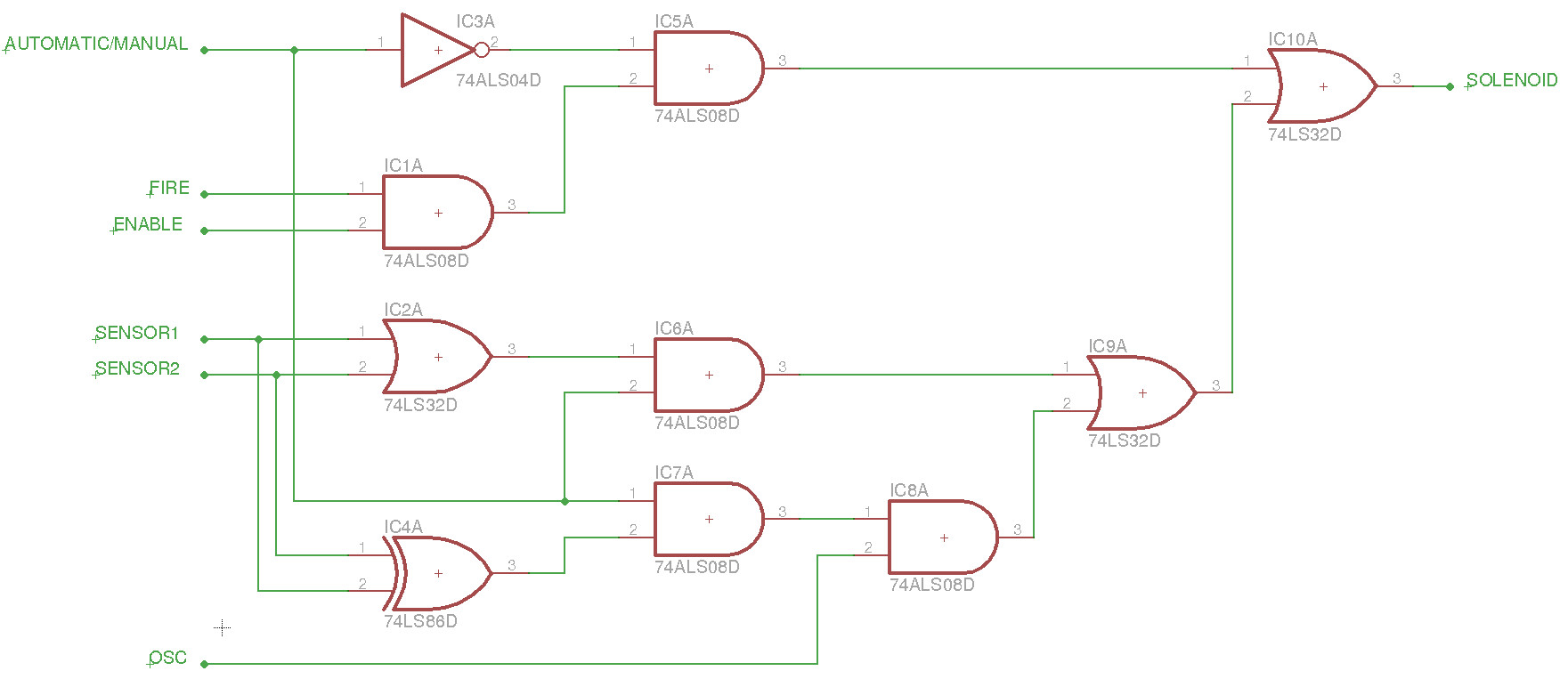
Figure 10 : Control circuit 2
Unfortunately the logic tutor board does not have a XOR gate, life is never easy :), but this oversight does allow for a little Boolean algebra so the actual implementation is shown in figure 11.
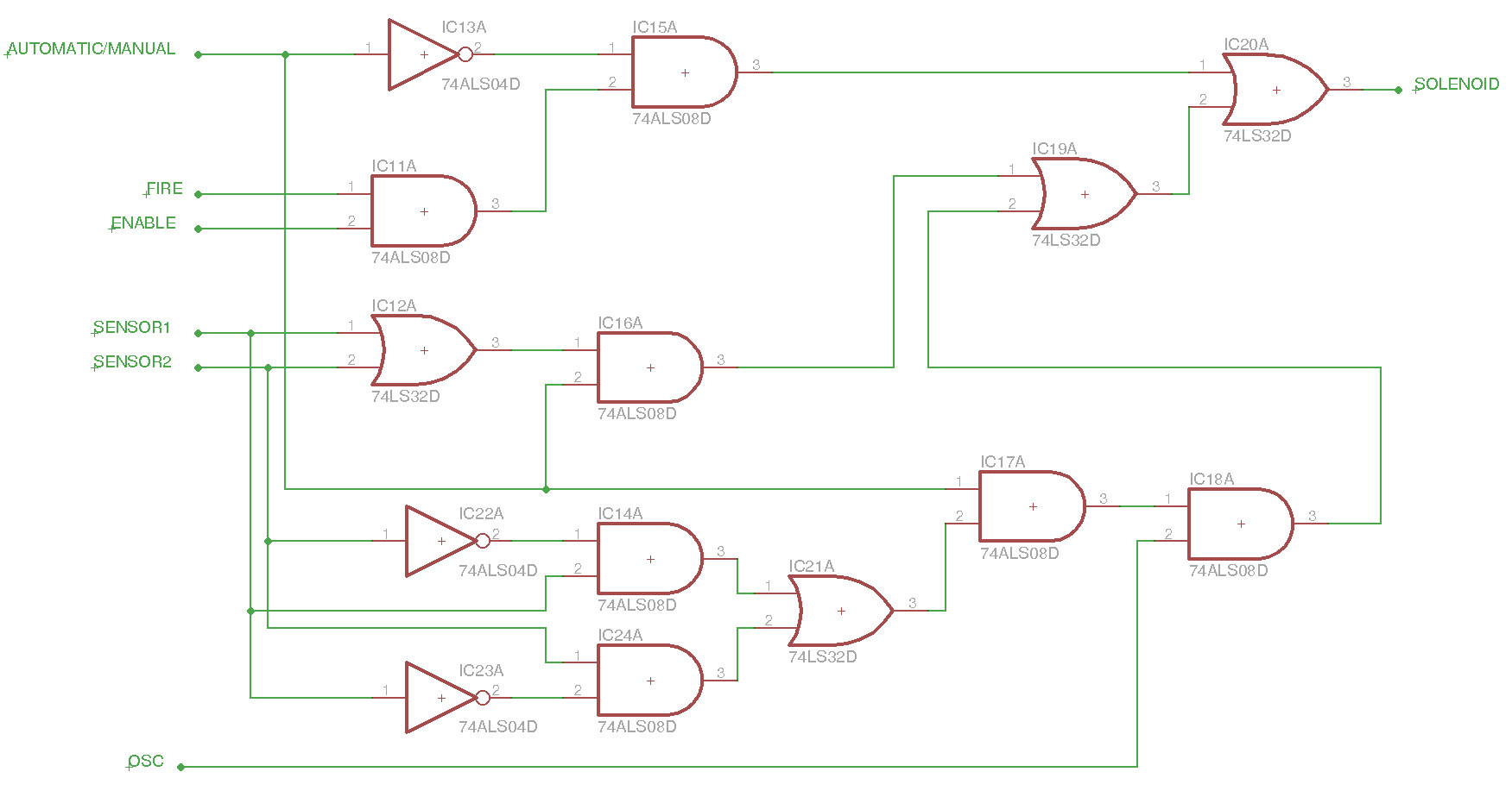
Figure 11 : Control circuit 3
Another small joy is there are only three 2-input AND gates and three 2-input OR gates, so the actual, actual circuit has to use 4-input AND/OR gates to implement these gates. Unused AND gate inputs can be tied to a logic 1, unused OR gate inputs can be tied to a logic 0, and to implement XOR gates the circuit in figure 12 can be used :).
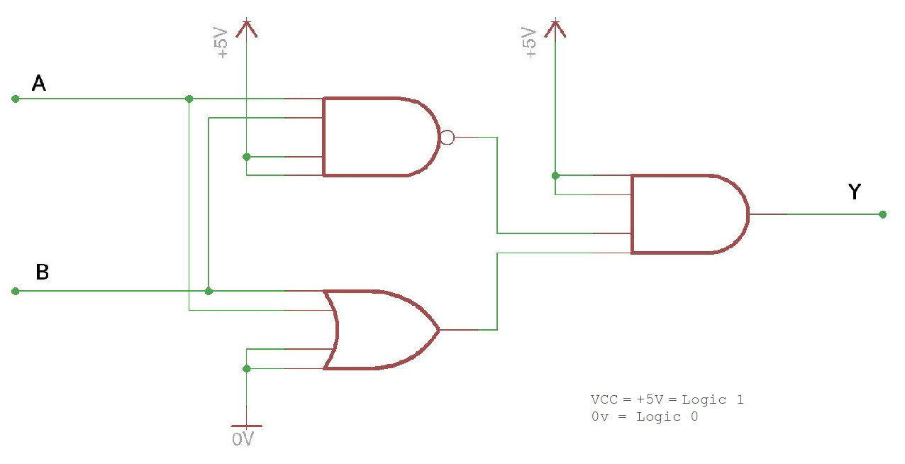
Figure 12 : alternative XOR gate implementation
The final bug trap implements a sequential logic circuit, the control rules shown below. The three second delay is required as the LDR sensors are on the edge of the trap, i.e. this delay would allow the bug to enter the trap and get to the bait in the middle before being crushed (maximise crushed area). Again, if the trap detects that the bug is trying to escape it stamps on the bug i.e. repeatedly opens and closes the trap. If the bug does escape, the trap is reset ready for the next bug. The final control circuit is shown in figure 13. This circuit is constructed from a 2bit binary counter, a SR flip-flop (JK, only using PRE and CLR) and control logic. When the bug enters the trap one of the LDR sensors is set to logic '1', enabling the counter and SR flip-flop. If the bug remains in the trap the counter will count up to 3 using the 1Hz clock i.e. a delay of approximately 3 seconds. The SR flip-flop is then set enabling the solenoid. If the bug then pushes through the trap both sensors are set to a logic '1' enabling stamping mode i.e. gates the solenoid signal with the clock.
IF BUG IN TRAP FOR > 3 SECONDS
THEN
	CLOSE TRAP
ELSE
	OPEN TRAP
END IF

IF TRAP CLOSED AND BUG TRIES TO ESCAPE
THEN
	STAMP ON BUG
END IF

IF NO BUG IN TRAP
THEN
	RESET COUNT
	OPEN TRAP
END IF
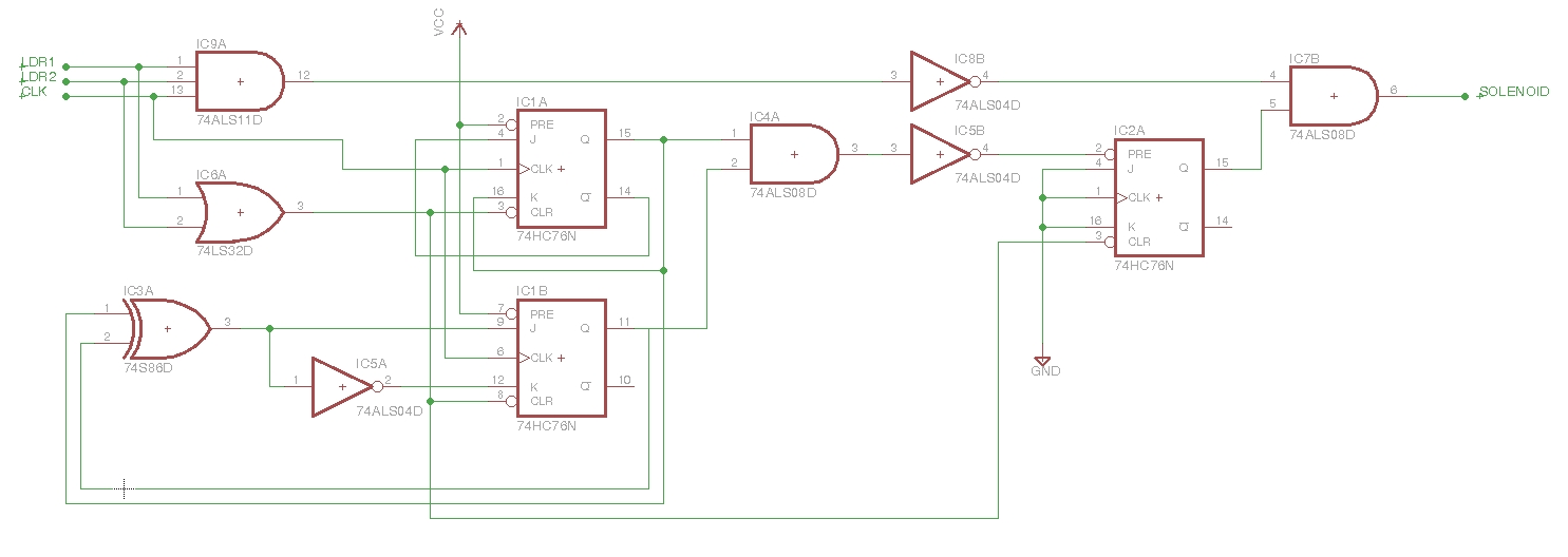
Figure 13 : Sequential logic circuit diagram
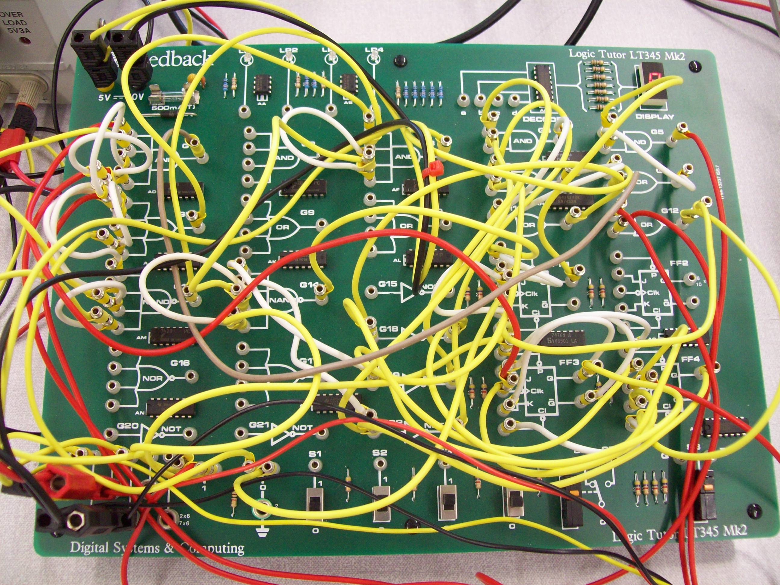
Figure 14 : Logic Tutor wiring
Some example lab scripts based on this hardware are available here:

This work is licensed under a Creative Commons Attribution-NonCommercial-NoDerivatives 4.0 International License.
Contact email: mike@simplecpudesign.com