A small increment, a small improvement, introducing the new SimpleCPUv1a1 processor. This version of the processor has been modified to include two new instructions: a conditional jump if carry set (JUMPC) and a rotate ACC one bit position right (ROTR). This processor was developed to illustrate how a processor is modified when new instructions are added to a processors instruction-set, the things you need to consider, the things you need to do. These new instructions are then used in a shift-&-add multiplication algorithm.
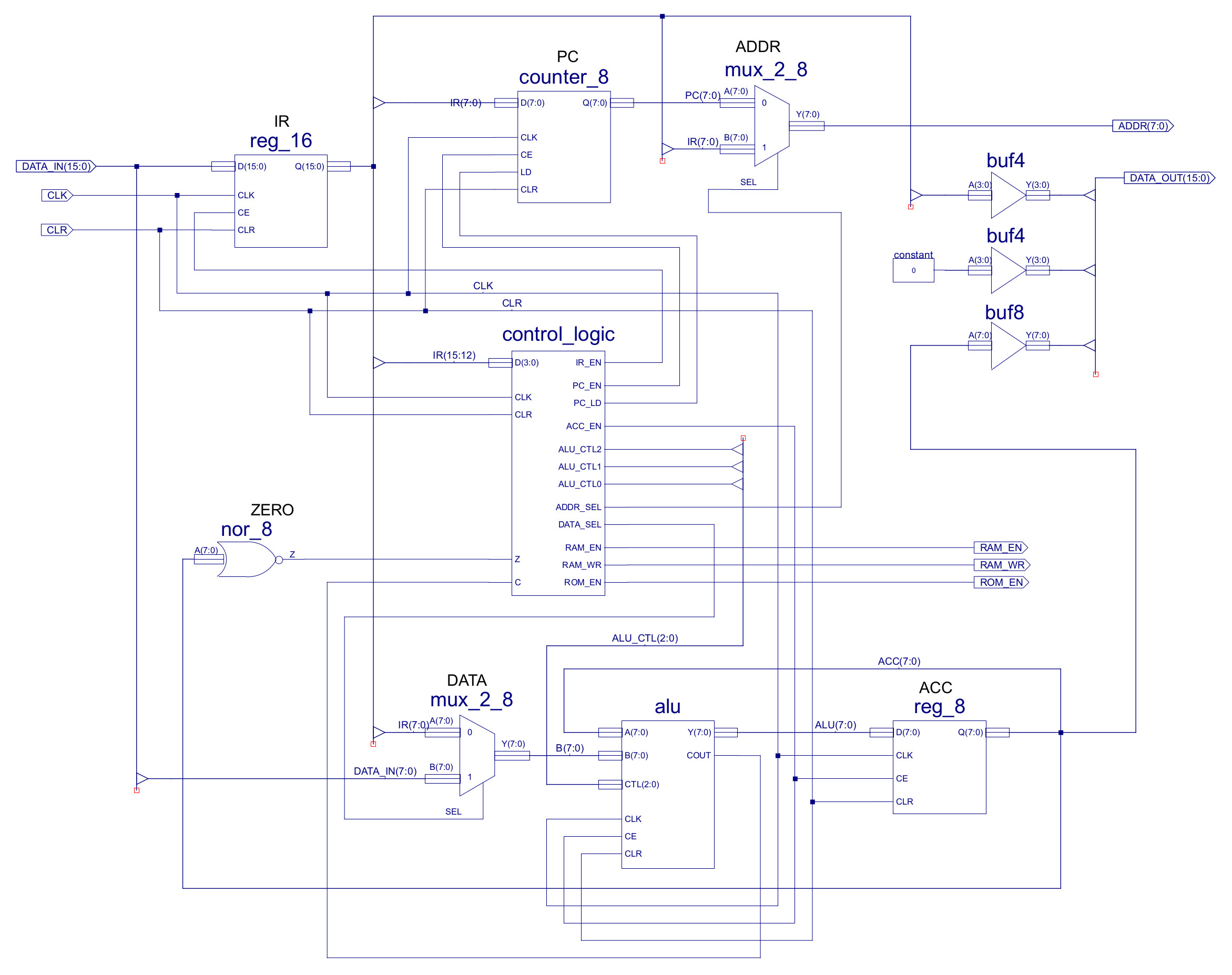
Figure 1 : processor
The new and improved ISE project files for this computer can be downloaded here: (Link). The main modification made to this processor is to the ALU, as shown in figure 1. The ALU is now clocked (CLK). This signal is not need by the functional components i.e. the rotate hardware, but rather the Carry flag (CFLAG). The carry flag like the zero flag are status bits indicating the result of the last arithmetic or logical operation. To keep things simple the simpleCPUs zero flag is based on the current result stored in the ACC i.e. driven by an 8bit NOR gate. Unfortunately, we can't use this simple logic based solution for the carry flag as its value would change as the operands entering the ALU change when the next instruction is fetched. Therefore, we need some memory, we need D-type flip-flop to remember the carry flags state. The carry flag is set by the addition and rotate hardware i.e. if an add instruction generates a 9bit result or if the rotate instruction moves a logic-1 in the LSB position into the carry flag, as illustrated by the RTL below:
Assembly : ROTR

RTL : ACC   <- CFLAG || ACC(7:1)
      CFLAG <- ACC(0)

Example       Description
move 0x11     ACC <= 00010001
              CFLAG <= 0
rotr          ACC <= 00001000
              CFLAG <= 1
rotr          ACC <= 10000100
              CFLAG <= 0
The carry flag is used to hold the LSB of the ACC that is shifted out of the ACC when the rotate right instruction is performed. This bit is stored in the carry flag until the next arithmetic or logical instruction is performed. A block diagram of how the ACC, rotate right hardware and carry flag are connected is shown in figure 2.
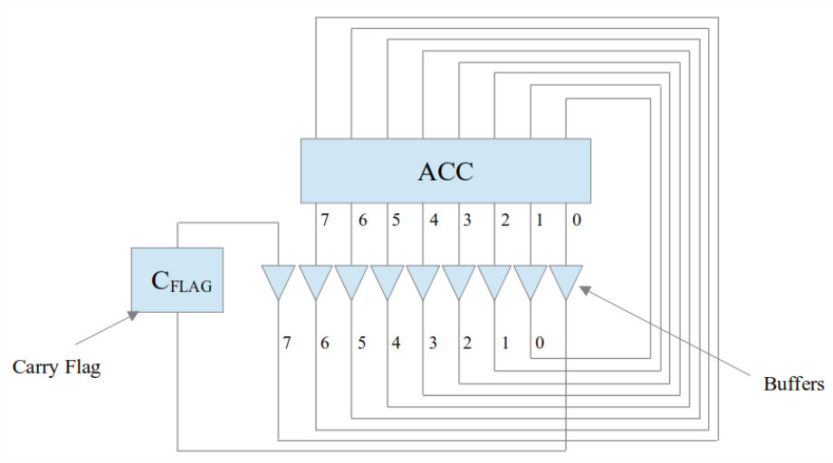
Figure 2 : rotate right block diagram
The carry flag is implemented in the ALU using a D-type flip-flop, as shown in figure 3, storing the state of this flag (COUT) between instructions. The four functional hardware components within the ALU i.e. add/sub, bitwise-and, pass-through and rotate, could all update this flag. However, in general most processors only allow arithmetic and logical instructions to update this flag i.e. MOVE, LOAD/STORE, JUMP instructions do not update the carry flag. This allows a bit more flexibility in software solutions. Therefore, for the simpleCPU_v1a1 the two main inputs to the carry flag are the add/sub and rotate hardware components. The carry signals from these components being selected by a four input bit-multiplexer.
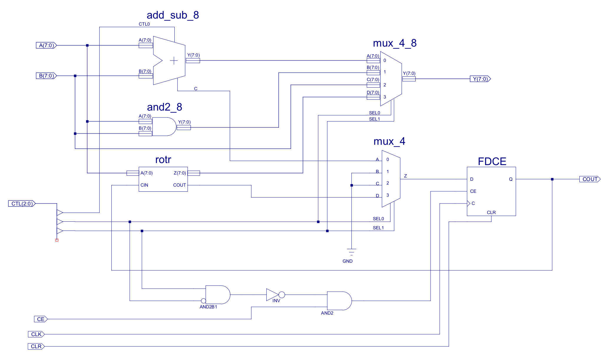
Figure 3 : arithmetic and logic unit (ALU)
The clock enable pin (CE) of the carry flag's D-type flip-flop is used to control when this flag is updated. This pin is controlled by the ALU's CE input port, that is in turn connected to the ACC's' CE line, as shown in figure 1. This signal is set to a logic '1' when the ACC is updated e.g. when an ADD or MOVE instruction is performed. However, to prevent the carry flag from being incorrectly updated when MOVE, LOAD/STORE, or JUMP instructions are executed a small amount of additional decode logic is added to the ALU.
The rotate right function is implemented using the hardware shown in figure 4. The required bit shift is simply implemented using "wires" i.e. input bit-6 is connected to output bit-5 etc. However, within ISE buffers are required as the you can't have a wire (signal) with two names i.e. a signal can not be called A(6) and Z(5). Input bit A(0) is "discarded" and used to drive the COUT pin. The new Z(7) output bit is drive from the CIN pin, which is driven by the carry flag, as shown in figure 3.
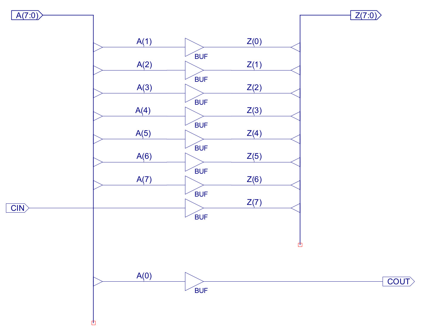
Figure 4 : rotate right hardware
The rotate right instruction (ROTR) is a zero operand instruction i.e. in the sense that no additional operands are needed, its functionality is hard-coded, always rotating the ACC contents one bit position to the right. The instruction format used is shown in figure 5. In theory only the 4-bit opcode (0xC)is need to represent this instruction in memory, "freeing" 12-bits of memory for other instructions. However, to simplify the processor's fetch phase i.e. align an instruction within a single memory location, rather than spreading instruction over two memory locations, the ROTR instruction uses the same 16bit fixed length instruction format as all other instructions. Therefore, the "operand" bit field is padded with 0's.
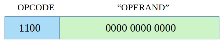
Figure 5 : ROTR instruction format
Within the processor this instruction is first processed by the decode-logic in the control_logic schematic shown in figure 6. The ROTR instruction has been assigned the opcode 0xC. Note, opcode 0xD has also been reserved for the rotate left (ROTL) instruction, but this has not been implemented. As the ROTR instruction does not need to process an operand stored in the IR or external memory the only control signals that need to be updated are those associated with the ACC update (ACC_EN) and ALU function selection (ALU_CTL). When the ROTR is loaded into the IR the YC pin from the onehot_decoder_16 component will be set to a logic 1 (all other outputs will be set to a logic 0). This signal can then be combined with existing signal using OR gates ("join" function) to control the ACC_EN and ALU_CTL signals. To select the ROTR hardware component output in the ALU (shown in figure 3) the ALU_CTL signal needs to be set to 11X i.e. ALU_CTL2=1, ALU_CTL1=1, ALU_CTL0=Don't care. These signals control the four-input MUXs within the ALU, driving the ROTR component's output onto the ALU's output bus.
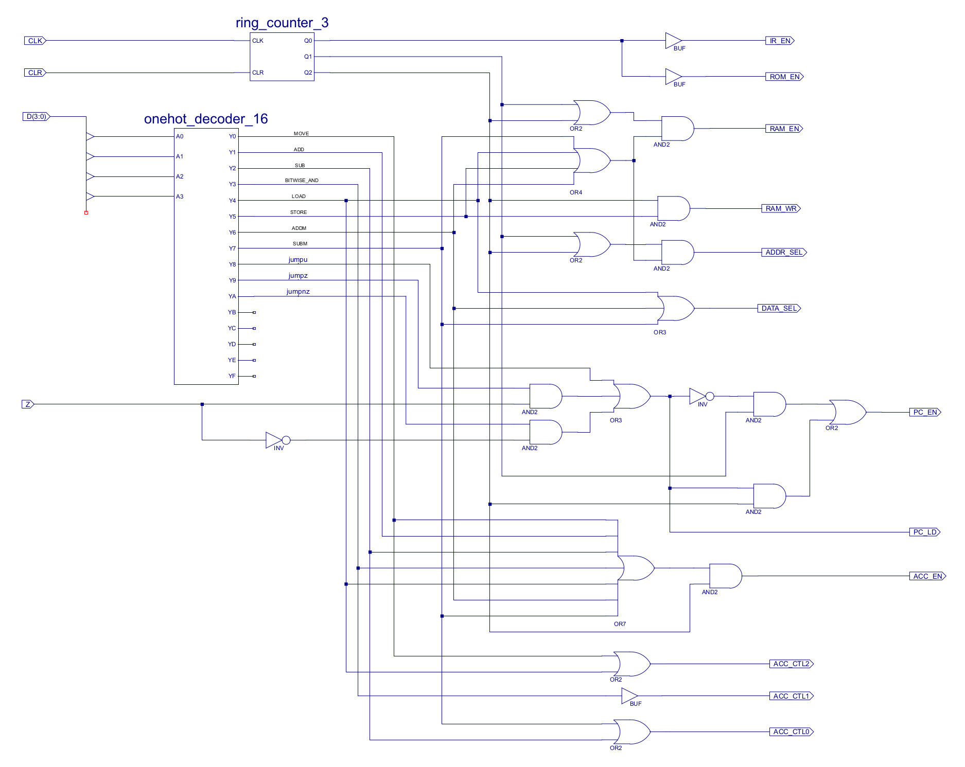
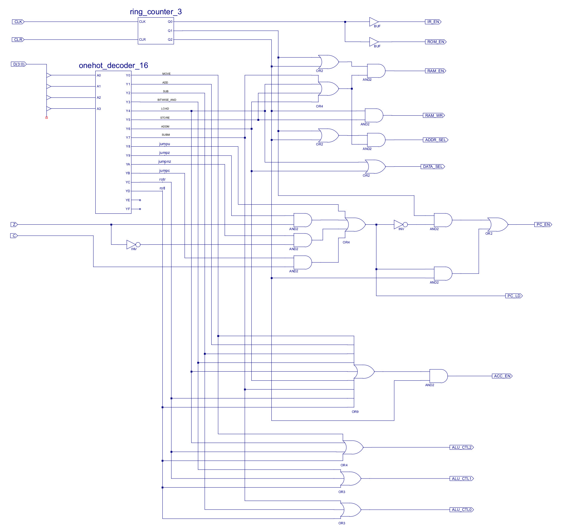
Figure 6 : control logic - original (top), new (bottom)
The second instruction added to the processor is a conditional jump instruction i.e. JUMPC. This jump instruction will jump to the absolute address specified in bit positions 7 to 0, if the carry flag is set, the bitfields used are shown in figure 7.
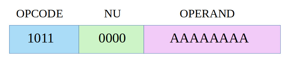
Figure 7 : JUMPC instruction format
To test if this new hardware and the existing hardware works the following test code was used:
#############
# TEST CODE #
#############

# Instructions
# ------------
# move, add, sub, and
# load, store, addm, subm
# jump / jumpu, jumpz, jumpnz, jumpc
# rotr
# .data

start:
  move 0xFF
  add 1
  add 1

  move 0
  sub 1
  sub 1

  move 10
  store A
  move 0
  load A
  move 0
  addm A
  move 0
  subm A

  move 1
  rotr
  rotr
  rotr
  rotr
  rotr
  rotr
  rotr
  rotr
  rotr

  move 0
  jumpnz end
  move 1
  jumpz end
  move 0
  jumpz next
  move 0xFF

next:
  move 1
  jumpnz next1
  move 0xFF

next1:
  move 0xFF
  add 1
  jumpc next2
  move 0xFF

next2:
  move 0
  add 1
  rotr
  jumpc end
  move 0xFF

end:
    jump end

A:
  .data 0
The results from this code can be seen in the simulation shown in figure 7. If you examine the debug section you can identify when the ROTR instructions are executed i.e. the value 1 is moved into the ACC, this is then repeatedly rotated right, updating the ACC with the values to 0x00, 0x80, 0x40, 0x20 ...
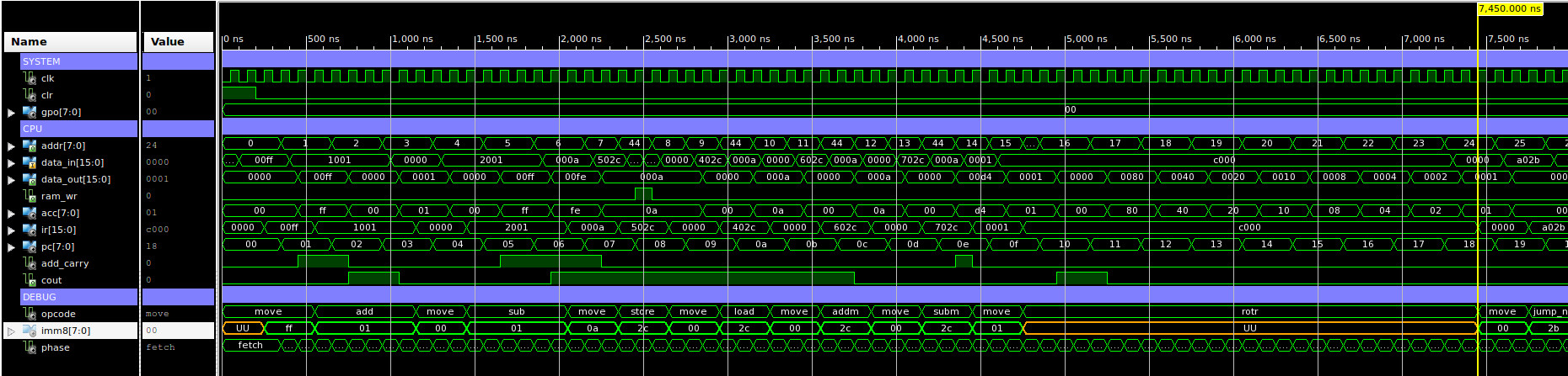
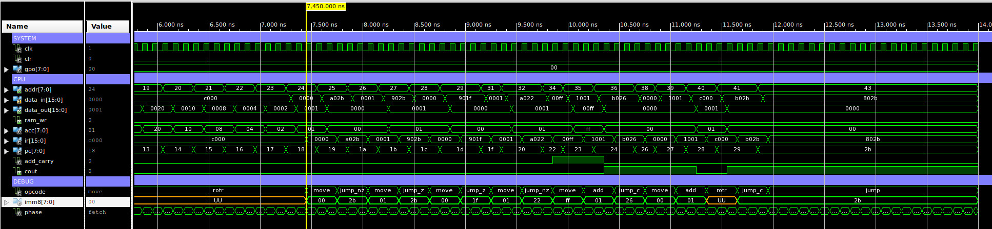
Figure 7 : test code simulation
Multiplication on the simpleCPU can be performed using repeated addition, however this is very inefficient. A more balanced algorithm can be implemented using shift and add instructions, as shown in figures 8 and 9. For more information on this algorithm refer to: (Link).
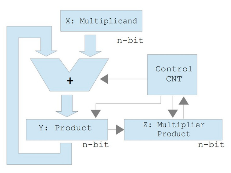
Figure 8 : shift and add block diagram
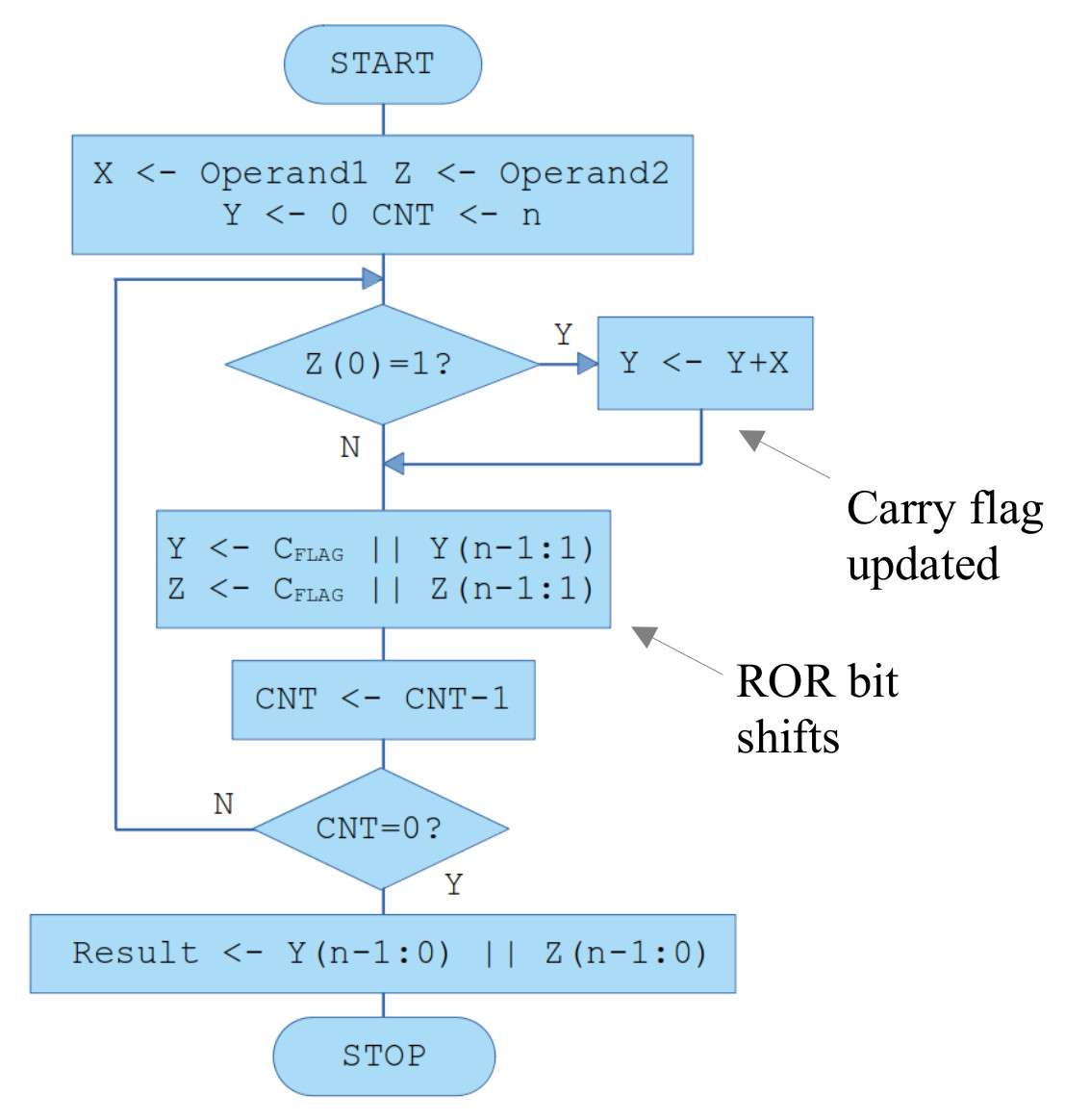
Figure 9 : shift and add block flowchart
Note, the two rotate operations highlight by the "ROR bit shifts" label are performed sequentially not in parallel i.e. the first rotate operation shifts the carry flag that was updated by the ADD instruction into the Y variable, rotating out Y(0) into the carry flag. This bit is then rotated into the multiplier variable Z, rotating out Z(0) into the carry flag, that is then dumped i.e. we only look at the multiplier LSB, the multiplier is incrementally overwritten by the low byte of the multiplication result.
The flow chart to perform the multiplication algorithm is shown in figure 9. The multiplicand is loaded into variable X, the multiplier into variable Z. The LSB of the multiplier is tested, if “1” the multiplicand is added to the partial product variable Y. Next, this partial product and the multiplier are shifted to the right. The LSB of the partial product variable overwriting the multiplier's MSB, as the multiplier is rotated to the right, ready to test the next bit position. This process is repeated until all bits within the multiplier have been tested. When complete the high byte of the result will be stored in variable Y and the low byte of the result in variable Z i.e. the 8bit variables Y and Z are used to store the 16bit result. Therefore, multiplication can now be performed using the ROTR and ADD instructions. Processing time is now proportion to the number of bits within the multiplier, rather than the multiplier's value.
The code to implement this multiplication algorithm is shown below:
#
# MAIN PROGRAM
#

start:
    move 8
    store CNT       # number of bits in multiplier

    move 255        # set multiplier
    store X
    move 0          # zero initial partial product
    store Y
    move 255        # set multiplicand
    store Z

loop:
    move 0          # clear carry flag
    add 0           # not needed, but just in case ADDER is updated to use CIN

    load Z          # test multiplier LSB
    and 1
    jumpz shiftY    # if zero shift

    load Y          # if one add multiplicand
    addm X
    rotr            # rotate Y
    store Y
    jump shiftZ

shiftY:
    load Y          # rotate Y
    rotr
    store Y
shiftZ:
    load Z          # rotate Z
    rotr
    store Z

dec:
    load CNT        # decrement and test loop count
    sub 1
    store CNT
    jumpnz loop

finish:
  load Y            # read result
  load Z
  jump finish

CNT:
    .data 0
X:
    .data 0
Y:
    .data 0
Z:
    .data 0
The results from this code can be seen in the simulation shown in figure 10. With a system clock speed of 10MHz the program takes approximately 44us to perform the calculation 255 * 255 = 65025 = 0xFE01, which is the result displayed in wave6, the last screen shot in the sequence below. Note, this value can not be loaded into the ACC in one chunk as the ACC is only 8bits wide, rather the 16bit value is stored in the variables Y and Z that are stored in external memory.
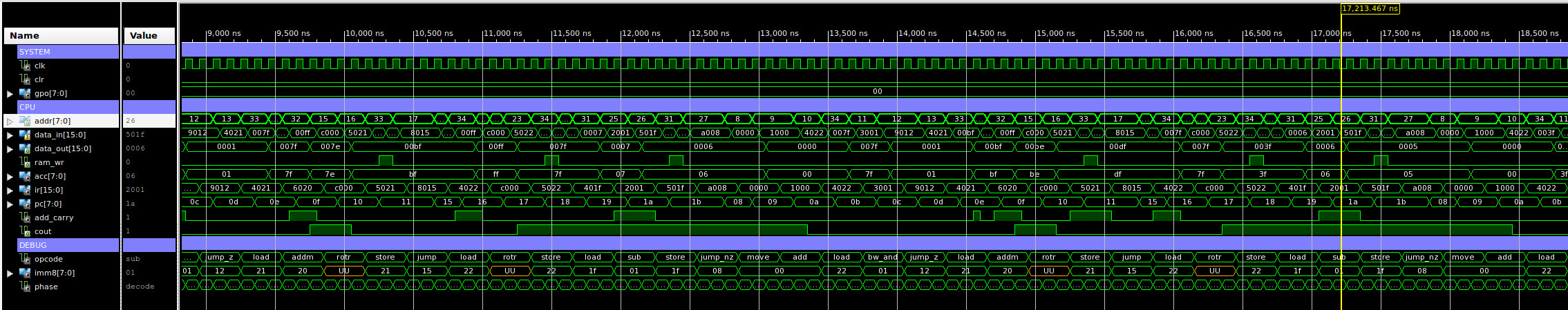
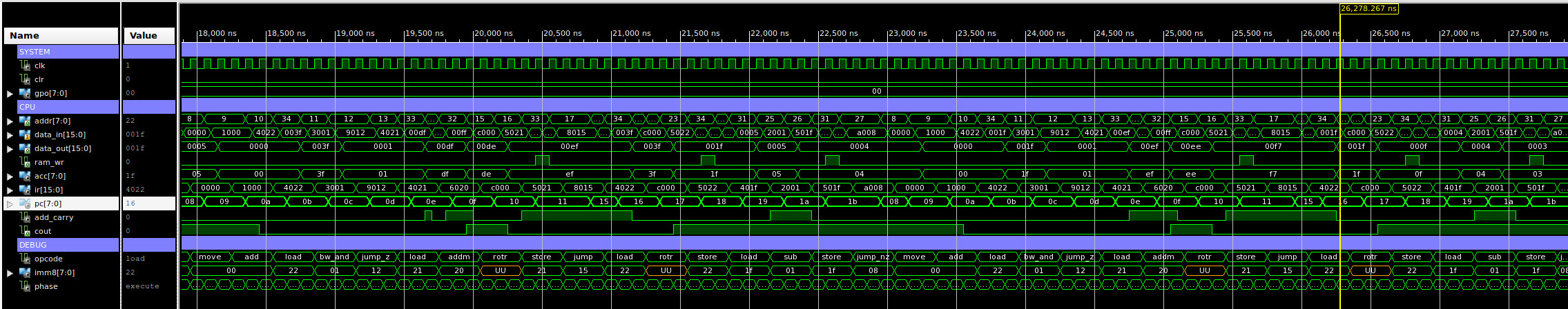
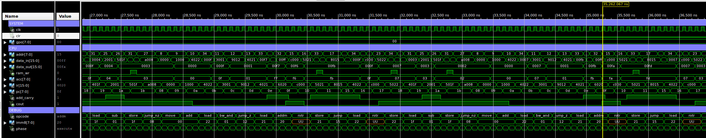
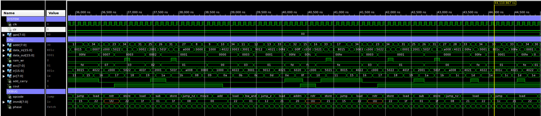
Figure 10 : test code simulation
Need to now write a good test program to illustrate the JUMPC instruction.
WORK IN PROGRESS

This work is licensed under a Creative Commons Attribution-NonCommercial-NoDerivatives 4.0 International License.
Contact email: mike@simplecpudesign.com