A summary of documents taken from SimpleCPU lectures, practicals and web pages, please refer back to these for more detailed information / explanation: (Link).
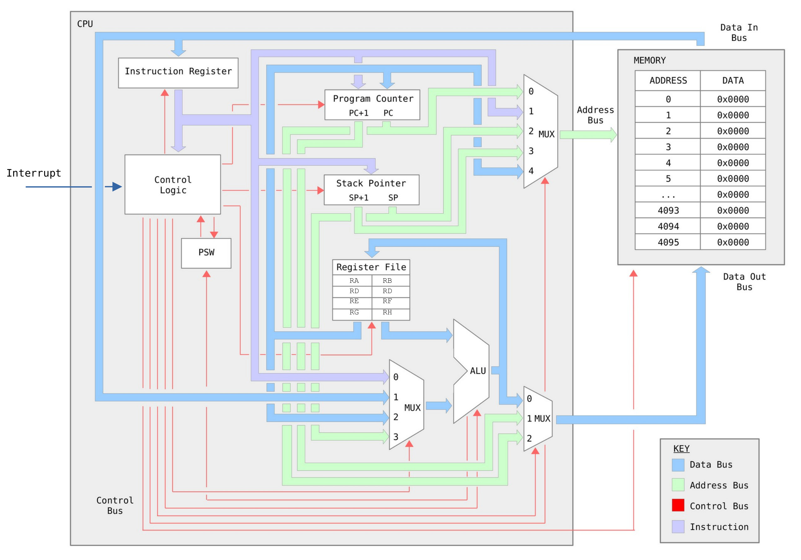
Figure 1 : SimpleCPU_v1e block diagram
This processor uses a fixed length 16bit instruction format. Memory is 4096 x 16bit, allowing an instruction to be stored in a single memory location. On reset the first instruction is fetched from address 0. The data processing unit i.e. ALU, is 16bit wide. The register file contains 8 x 16bit general purpose registers: RA - RH. The CALL-RET stack is implemented in external memory, accessed via the stack pointer (SP) register. Push / Pop instruction can be used to pass parameter and results between subroutines / main program. If stack frames are used the general purpose register RH should be reserved as the frame pointer. This processor supports interrupts. Multiple levels of interrupts are supported using an external interrupt controller. The interrupt vector address is defined as a constant within the ISE schematic and may be changed by the user. The interrupt return address is automatically stored on the CALL-RET stack, however, the user is responsible for check-pointing / restoring any registers used by the interrupt service routine (ISR). To simplify the hardware implementation this CPU has separate 16bit data-in and data-out buses. This processor does not support byte addressable memory.
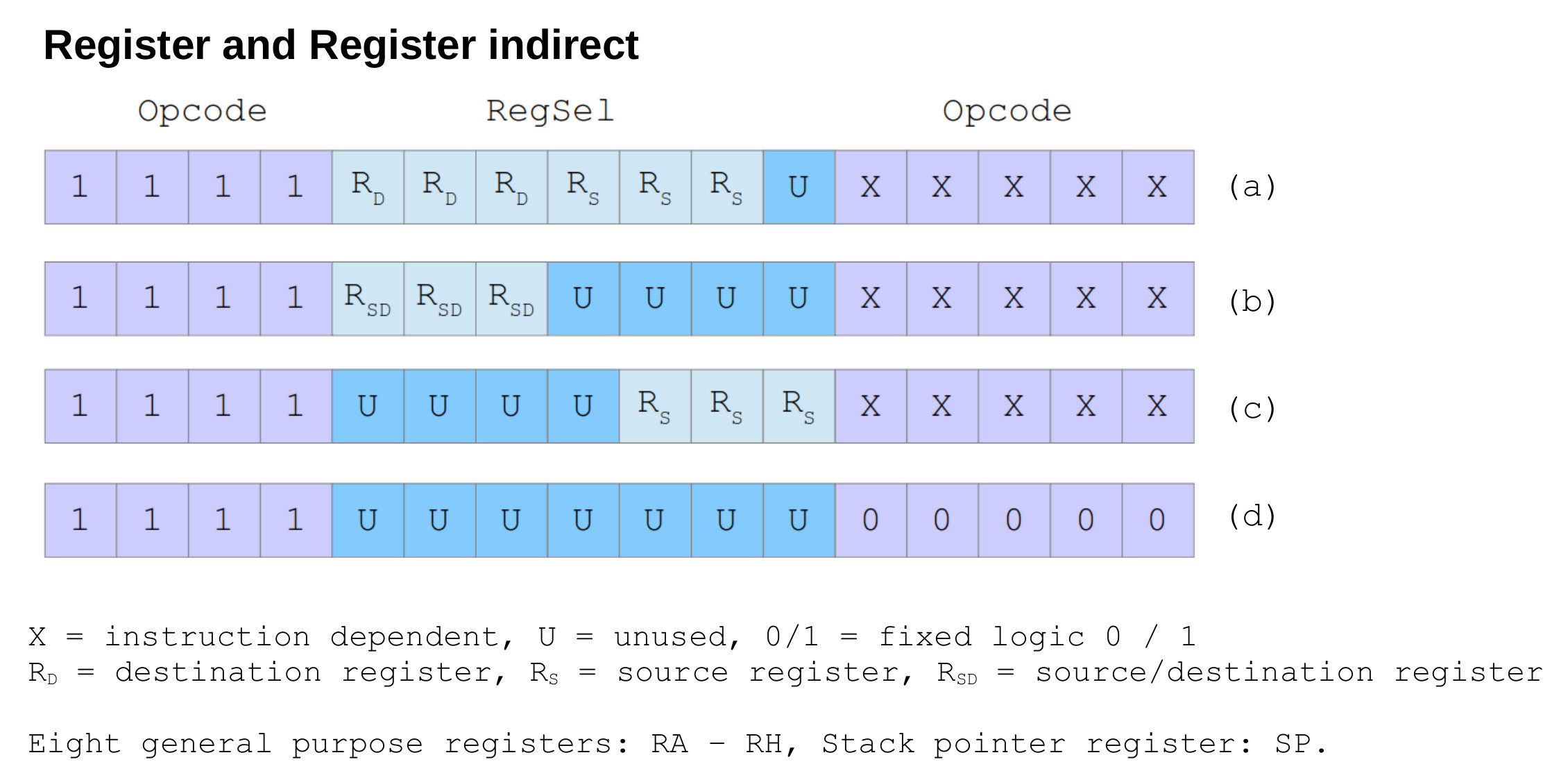
Figure 2 : instruction formats - Register and Register-indirect
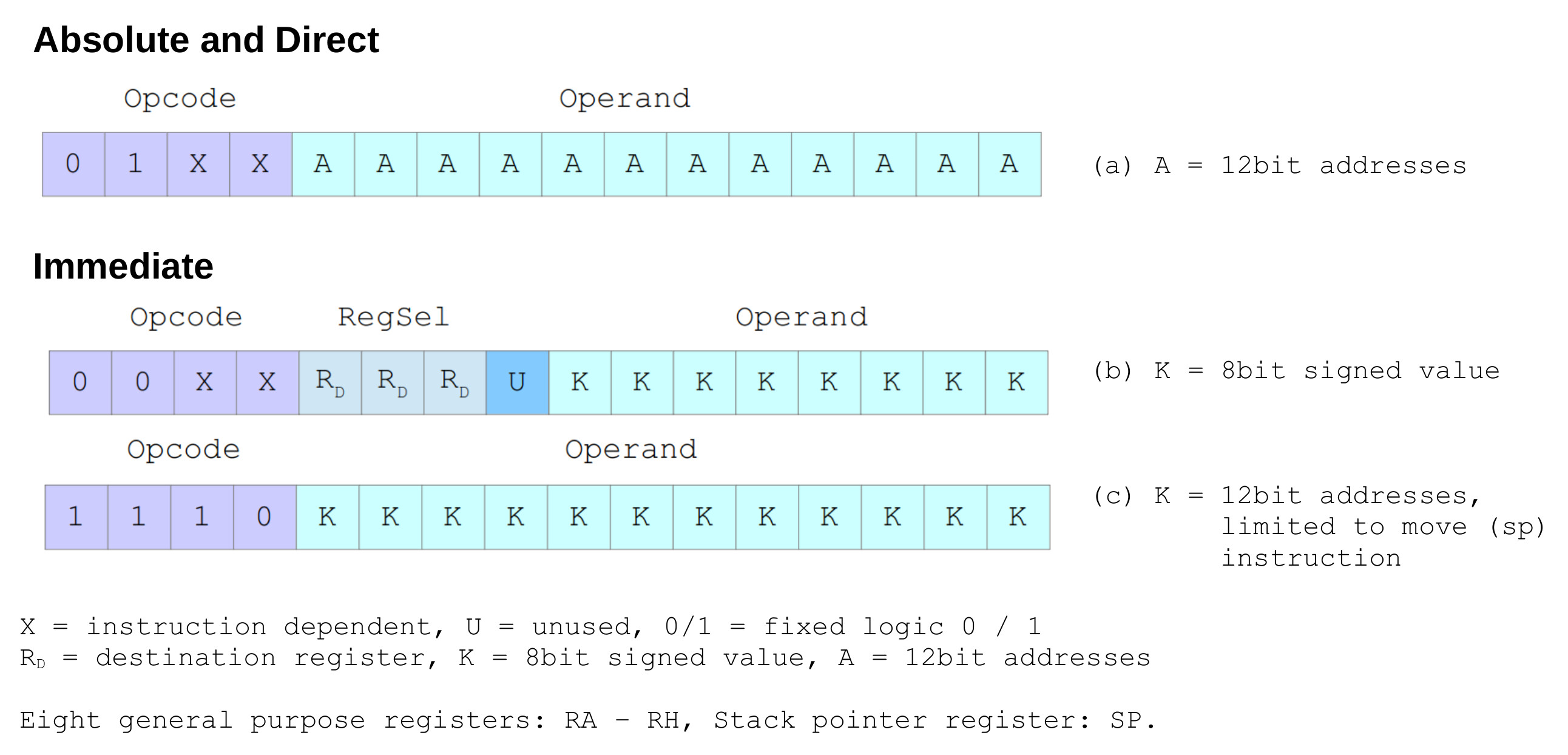
Figure 3 : instruction formats - Absolute, Direct and Immediate
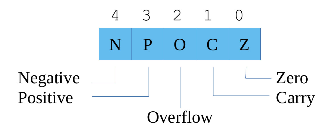
Figure 4 : status register, flags
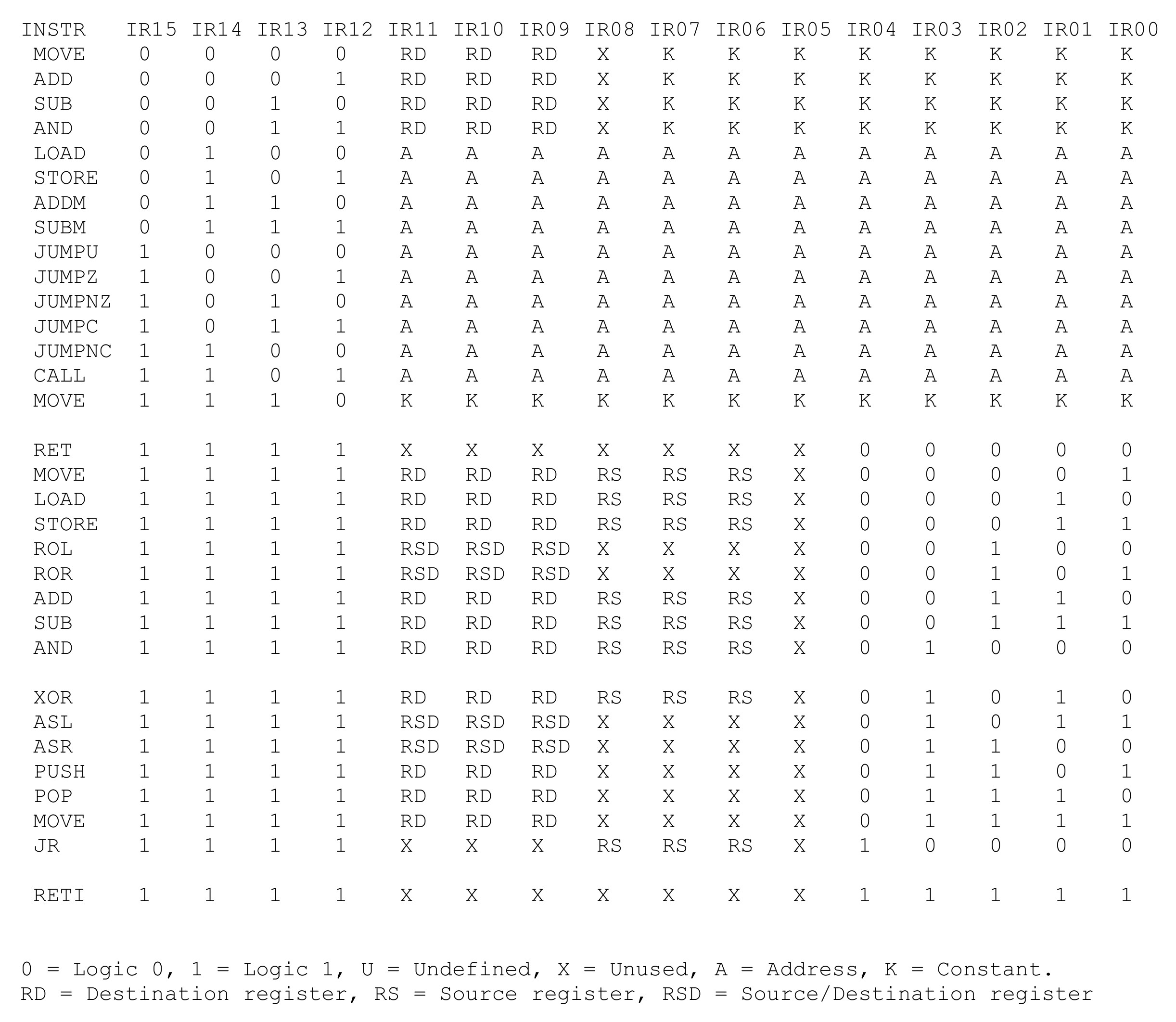
Figure 5 : instruction bit fields
Example            :    move RA 1
Addressing mode    :    immediate
Opcode             :    0000
RTL                :    RX <- ( (K7)8 || KK )
Flags set          :     None
Move signed 8bit value into general purpose register. The bit field KK is as defined in figure 3b. In this example RX is register RA and KK is the value 1, signed extended to 16bits. Therefore, at the end of the execution phase register RA=1.
Example            :    add RB 2
Addressing mode    :    immediate
Opcode             :    0001
RTL                :    RX <- RX + ( (K7)8 || KK )
Flags set          :    Z,C,O,P,N
Add signed 8bit value to general purpose register. The bit field KK is as defined in figure 3b. In this example RX is register RB and KK is the value 2, signed extended to 16bits. Therefore, if RB=1 at the end of the execution phase register RB=3.
Example            :    sub RC 3
Addressing mode    :    immediate
Opcode             :    0010
RTL                :    RX <- RX - ( (K7)8 || KK )
Flags set          :    Z,C,O,P,N
Subtract signed 8bit value from general purpose register. The bit field KK is as defined in figure 3b. In this example RX is register RC and KK is the value 3, signed extended to 16bits. Therefore, if RC=5 at the end of the execution phase register RC=2.
Example            :    and RD 4
Addressing mode    :    immediate
Opcode             :    0011
RTL                :    RX <- RX & ( (0)8 || KK )
Flags set          :    Z,C,O,P,N
Perform 8bit bitwise AND on general purpose register. The bit field KK is as defined in figure 3b. In this example RX is register RD and KK is the value 4. Therefore, if RD=7 at the end of the execution phase register RD=4. Note, KK represents a binary pattern, this data is not sign extended.
Example            :    load RA 123
Addressing mode    :    absolute
Opcode             :    0100
RTL                :    RA <- M[AAA]
Flags set          :    None
Transfer a 16bit value from memory to general purpose register RA. The bit field AAA is as defined in figure 3a. In this example AAA is the address 123, therefore, if M[123]=10 at the end of the execution phase register RA=10. Note, the destination register is hardwired to register RA, you can not use other registers.
Example            :    store RA 234
Addressing mode    :    absolute
Opcode             :    0101
RTL                :    M[AAA] <- RA
Flags set          :    None
Store 16bit value in general purpose register RA to memory. The bit field AAA is as defined in figure 3a. In this example AAA is the address 234, therefore, if RA=9 at the end of the execution phase memory location M[234]=9. Note, the source register is hardwired to register RA, you can not use other registers.
Example            :    addm RA 345
Addressing mode    :    absolute
Opcode             :    0110
RTL                :    RA <- RA + M[AAA]
Flags set          :    Z,C,O,P,N
Add 16bit value stored in memory to general purpose register RA. The bit field AAA is as defined in figure 3a. In this example AAA is the address 345, therefore, if RA=20 and M[345]=10 at the end of the execution phase register RA=30. Note, the destination register is hardwired to register RA, you can not use other registers.
Example            :    subm RA 456
Addressing mode    :    absolute
Opcode             :    0111
RTL                :    RA <- RA - M[AAA]
Flags set          :    Z,C,O,P,N
Subtract 16bit value stored in memory from general purpose register RA. The bit field AAA is as defined in figure 3a. In this example AAA is the address 456, therefore, if RA=20 and M[456]=10 at the end of the execution phase register RA=10. Note, the destination register is hardwired to register RA, you can not use other registers.
Example            :    jump 200
Addressing mode    :    direct
Opcode             :    1000
RTL                :    PC <- AAA
Flags set          :    None
Unconditional jump. The bit field AAA is as defined in figure 3a. In this example AAA is the address 200, at the end of the execution phase the PC is updated to 200.
Example            :    jumpz 201
Addressing mode    :    direct
Opcode             :    1001
RTL                :    IF Z=1 THEN PC <- AAA ELSE PC <- PC + 1
Flags set          :    None
Jump if last arithmetic or logical instruction produced a zero result i.e. jump is conditional on the status register’s Z flag. The bit field AAA is as defined in figure 3a. In this example AAA is the address 201. If Z=1 the PC is set to the value 201 at the end of the execution phase, else PC+1. Note, status register (Z flag) is only updated by arithmetic or logical instructions.
Example            :    jumpnz 202
Addressing mode    :    direct
Opcode             :    1010
RTL                :    IF Z=0 THEN PC <- AAA ELSE PC <- PC + 1
Flags set          :    None
Jump if last arithmetic or logic instruction did not produce a zero result i.e. jump is conditional on the status register’s Z flag. The address AAA is as defined in figure 3. In this example AAA is the address 202. If Z=0 the PC is set to the value 202 at the end of the execution phase, else PC+1. Note, status register (Z flag) is only updated by arithmetic or logical instructions.
Example            :    jumpc 203
Addressing mode    :    direct
Opcode             :    1011
RTL                :    IF C=1 THEN PC <- AAA ELSE PC <- PC + 1
Flags set          :    None
Jump if last arithmetic instruction generated a carry i.e. jump is conditional on the status register’s C flag. The bit field AAA is as defined in figure 3a. In this example AAA is the address 203, if C=1 the PC is set to the value 203 at the end of the execution phase, else PC+1. Note, status register (C flag) is only updated by arithmetic instructions.
Example            :    jumpnc 204
Addressing mode    :    direct
Opcode             :    1100
RTL                :    IF C=0 THEN PC <- AAA ELSE PC <- PC + 1
Flags set          :    None
Jump if last arithmetic instruction generated a carry i.e. jump is conditional on the status register’s C flag. The bit field AAA is as defined in figure 3a. In this example AAA is the address 204. If C=0 the PC is set to the value 204 at the end of the execution phase, else PC+1. Note, status register (C flag) is only updated by arithmetic instructions.
Example            :    call 300
Addressing mode    :    direct
Opcode             :    1101
RTL                :    M[SP]<- PC + 1
                   :    SP <- SP - 1
                   :    PC <- AAA
Flags set          :    None
Call subroutine. The bit field AAA (subroutine address) is as defined in figure 3a. In this example AAA is the address 300. If PC=100 and SP=2000, at the end of the execution phase the PC is updated to 300 and SP=1999. The return address 101 is written to top of stack, as defined by the stack pointer (SP) register. Note, the CALL-RETURN stack is stored in external memory.
Example            :    move SP 400
Addressing mode    :    immediate
Opcode             :    1110
RTL                :    SP <- KKK
Flags set          :    None
Move 12bit value into stack pointer (SP) register. The bit field KKK is as defined in figure 3c. In this example KKK is the address 400, therefore, at the end of the execution phase the stack pointer is updated to 400. Note, this 12bit addressing mode is not permitted for general purpose registers.
Example            :    ret
Addressing mode    :    implicit
Opcode             :    1111 + 00000
RTL                :    SP <- SP + 1
                   :    PC <- STACK[SP]
Flags set          :    None
Return from subroutine. Higher and lower opcode values as defined in figure 2d. At the end of the execution phase the PC will be updated to the return address at stack address SP-1. If M[SP-1]=101 and SP=1999, at the end of the execution phase the PC is updated to 101 and SP=2000. Note, the CALL-RETURN stack is stored in external memory.
Example            :    move ra rb
Addressing mode    :    register
Opcode             :    1111 + 00001
RTL                :    RX <- RY
Flags set          :    None
Transfer a 16bit value from source to destination general purpose register. Higher and lower opcode values as defined in figure 2a. In this example RX is register RA and RY is register RB. If RB=1 and RA=100 at the end of the execution phase register RA=1.
Example            :    load ra (rb)
Addressing mode    :    register indirect
Opcode             :    1111 + 0010
RTL                :    RX <- M[RY]
Flags set          :    None
Transfer a 16bit value from memory to destination general purpose register. Accessed memory address stored in general purpose register enclosed by brackets. Higher and lower opcode values as defined in figure 2a. In this example RX is register RA and RY is register RB. If RB=100 and M[100]=5, therefore, at the end of the execution phase register RA=5.
Example            :    store rb (rc)
Addressing mode    :    register indirect
Opcode             :    1111 + 00011
RTL                :    M[RY] <- RX
Flags set          :    None
Transfer a 16bit value from general purpose register to memory. Accessed memory address stored in general purpose register enclosed by brackets. Higher and lower opcode values as defined in figure 2a. In this example RX is register RB and RY is register RC. If RB=10 and RC=100, therefore, at the end of the execution phase memory location M[100]=10.
Example            :    rol rb
Addressing mode    :    register
Opcode             :    1111 + 00100
RTL                :    RX <- ( RX(14:0) || RX(15) )
Flags set          :    Z,C,O,P,N
Rotate bits within general purpose register one position to the left. Higher and lower opcode values as defined in figure 2b. In this example RX is register RB, therefore, if RB=2 at the end of the execution phase register RB=4.
Example            :    ror rb
Addressing mode    :    register
Opcode             :    1111 + 00101
RTL                :    RX <- ( RX(0) || RX(15:1) )
Flags set          :    Z,C,O,P,N
Rotate bits within general purpose register one position to the right. Higher and lower opcode values as defined in figure 2b. In this example RX is register RB, therefore, if RB=2 at the end of the execution phase register RB=1.
Example            :    add ra rb
Addressing mode    :    register
Opcode             :    1111 + 00110
RTL                :    RX <- RX + RY
Flags set          :    Z,C,O,P,N
Add 16bit value in source general purpose register to destination general purpose register. Higher and lower opcode values as defined in figure 2a. In this example RX is register RA and RY is register RB, therefore, if RA=20 and RB=10 at the end of the execution phase register RA=30.
Example            :    sub ra rb
Addressing mode    :    register
Opcode             :    1111 + 00111
RTL                :    RX <- RX - RY
Flags set          :    Z,C,O,P,N
Subtract 16bit value in source general purpose register from destination general purpose register. Higher and lower opcode values as defined in figure 2a. In this example RX is register RA and RY is register RB, therefore, if RA=25 and RB=10 at the end of the execution phase register RA=15.
Example            :    and ra rb
Addressing mode    :    register
Opcode             :    1111 + 01000
RTL                :    RX <- RX & RY
Flags set          :    Z,C,O,P,N
Perform bitwise AND on 16bit source and destination values in general purpose registers. Higher and lower opcode values as defined in figure 2a. In this example RX is register RA and RY is register RB, therefore, if RA=15 and RB=7 at the end of the execution phase register RA=7.
Example            :    xor ra rb
Addressing mode    :    register
Opcode             :    1111 + 01010
RTL                :    RX <- RX + RY
Flags set          :    Z,C,O,P,N
Perform bitwise XOR on 16bit source and destination values in general purpose registers. Higher and lower opcode values as defined in figure 2a. In this example RX is register RA and RY is register RB, therefore, if RA=7 and RB=2 at the end of the execution phase register RA=5.
Example            :    asl rb
Addressing mode    :    register
Opcode             :    1111 + 01011
RTL                :    RX <- ( RX(14:0) || 0 )
Flags set          :    Z,C,O,P,N
Arithmetic shift left, shift bits in general purpose register one position to the left inserting 0 into LSB. Higher and lower opcode values as defined in figure 2b. In this example RX is register RB, therefore, if RB=10 at the end of the execution phase register RB=20.
Example            :    asr rb
Addressing mode    :    register
Opcode             :    1111 + 01100
RTL                :    RX <- ( 0 || RX(15:1) )
Flags set          :    Z,C,O,P,N
Arithmetic shift right, shift bits in general purpose register one position to the right inserting 0 into MSB. Higher and lower opcode values as defined in figure 2b. In this example RX is register RB, therefore, if RB=10 at the end of the execution phase register RB=5.
Example            :    push rb
Addressing mode    :    register
Opcode             :    1111 + 01101
RTL                :    M[SP] <- RX
                        SP <- SP - 1
Flags set          :    None
Store the value in general purpose register to top of stack, as defined by the stack pointer (SP) register. Higher and lower opcode values as defined in figure 2b. In this example RX is register RB, therefore, if RB=10 and SP=2000 at the end of the execution phase M[2000]=10 and SP=1999. Note, this stack is stored in external memory.
Example            :    pop rb
Addressing mode    :    register
Opcode             :    1111 + 01110
RTL                :    SP <- SP + 1
                        RX <- M[SP]
Flags set          :    None
Save the value stored in top of stack, as defined by the stack pointer (SP) register, to general purpose register. Higher and lower opcode values as defined in figure 2b. In this example RX is register RB, therefore, if SP=1999 and M[2000]=10 at the end of the execution phase RB=10 and SP=2000. Note, this stack is stored in external memory.
Example            :    move rb sp
Addressing mode    :    register
Opcode             :    1111 + 01111
RTL                :    RX <- SP
Flags set          :    None
Copy the value stored in the stack pointer (SP) register to a general purpose register. Higher and lower opcode values as defined in figure 2b. In this example RX is register RB. If SP=2000 at the end of the execution phase register RB=2000.
Example            :    jr rb
Addressing mode    :    register
Opcode             :    1111 + 10000
RTL                :    PC <- RX
Flags set          :    None
Unconditional jump. The branch target address is as defined in figure 2c. In this example AAA is the address 200, at the end of the execution phase the PC is updated to 200.
Example            :    reti
Addressing mode    :    implicit
Opcode             :    1111 + 00000
RTL                :    SP <- SP - 1
                   :    PC <- STACK[SP]
Flags set          :    None
Return from subroutine. Higher and lower opcode values as defined in figure 2d. At the end of the execution phase the PC will be updated to the return address at stack address SP-1. If M[SP-1]=101 and SP=2001, at the end of the execution phase the PC is updated to 101 and SP=2000. Note, the CALL-RETURN stack is stored in external memory.
Pseudo Code             Assembler code                Notes
IF A=0                  start:                        variable A is stored in register
THEN                        and RA 0xFF               RA and is 8bits. Variable B is
    B = 10                  jumpz    zero             stored in RB and is 8bits.
ELSE                    notZero:
    B = 20                  move rb 20
END IF                      jump exit
                        zero:
                            move rb 10
                        exit:
                            jump exit
Pseudo Code             Assembler code                Notes
IF A=B                  start:                        variable A is stored in register
THEN                       subm RA 100                RA, variable B is stored in M[100]
    C = 10                 jumpz    equal             and variable C is stored in M[101]
ELSE                    notEqual:
    C = 20                 move RA 20
END IF                     store RA 101
                           jump exit
                        equal:
                           move RA 10
                           store RA 101
                        exit:
                           jump exit
Pseudo Code             Assembler code                Notes
IF A<B                  start:                        variable A is stored in register
THEN                        subm RA 100               RA, variable B is stored in M[100]
    C = 10                  rol RA                    and variable C is stored in M[101]
ELSE                        and RA 0x1
    C = 20                  jumpnz less
END IF                  greater:
                            move RA 10
                            store RA 101
                           jump exit
                        less:
                            move RA 20
                            store RA 101
                        exit:
                            jump exit
Pseudo Code                 Assembler code                Notes
FOR I in {0..4}             start:                        variable I is stored in
DO                              move RD 4                 register RD and variable A
    A = A + 1                   move RA 0                 in register RA. Loop count is
DONE                        loop:                         an 8bit value.
                                and RD 0xFF
                                jumpz exit
                                add RA 1
                                sub RD 1
                                jump loop
                            exit:
                                jump exit
Pseudo Code                  Assembler code                Notes
WHILE (A<10)                 start:                        variable RA stored in register
DO                              move RA 0                  RA and is an 8bit value.
    A = A + 1                loop:
DONE                            move RB RA
                                sub RB 10
                                jumpz exit
                                add RA 1
                                jump loop
                            exit:
                                jump exit
Pseudo Code                 Assembler code                Notes
A = 100                     start:                        move instruction limited to a
B = 1000                        move RA 0x64              signed 8bit value. Variables A
C = 10000                       move RB 0x3E              and B are stored in registers
D = 65535                       rol RB                    RA and RB. Variables C and D
                                rol RB                    stored in memory.
                                rol RB
                                rol RB
                                add RB 8
                                move RC 0x27
                                rol RC
                                rol RC
                                rol RC
                                rol RC
                                rol RC
                                rol RC
                                rol RC
                                rol RC
                                add RC 0x10
                                store RC C

                            exit:
                                jump exit

                            C:
                                .data 0
                            D:
                                .data 0xFFFF

This work is licensed under a Creative Commons Attribution-NonCommercial-NoDerivatives 4.0 International License.
Contact email: mike@simplecpudesign.com