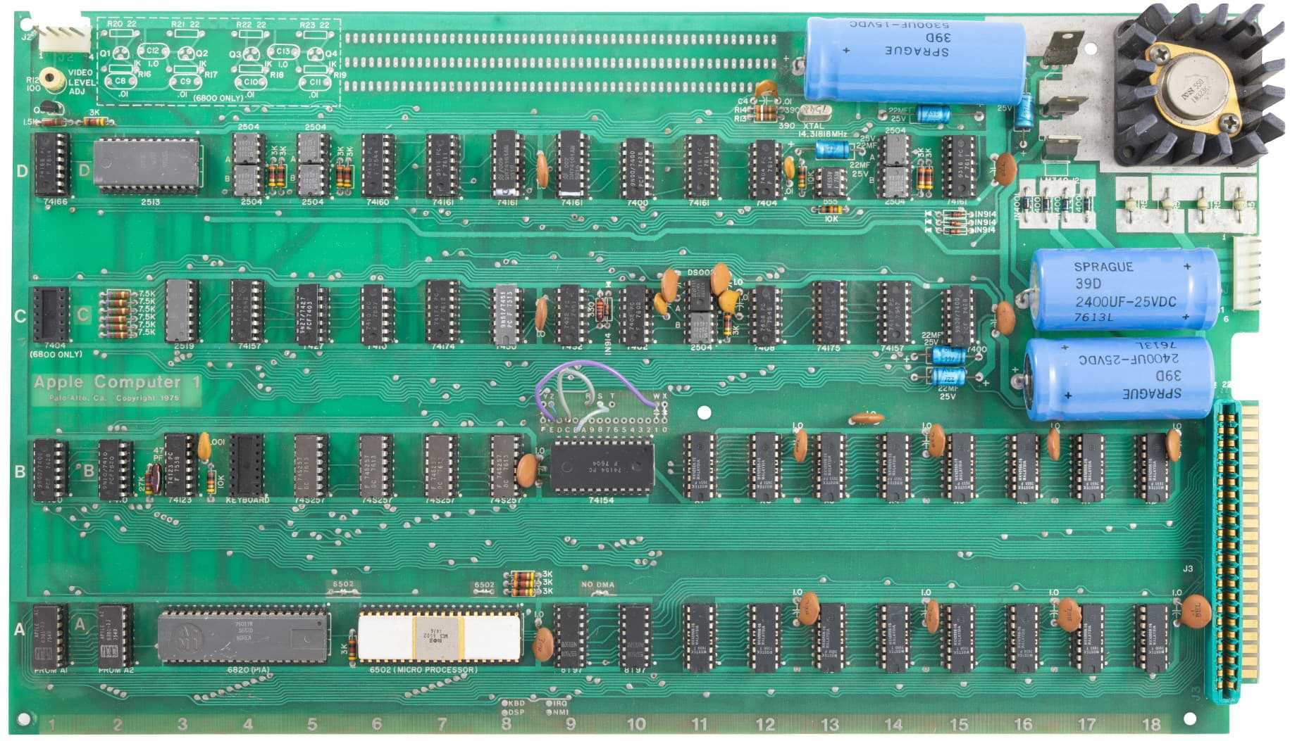
Figure 1 : Apple I computer
Programs on the simpleCPU are best described as bare metal software, code that runs directly on physical hardware without an underlying operating system i.e. your program is the only code in the processor's memory, having direct unrestricted access to the processor's registers, memory and peripherals. This arrangement is fine for application specific systems designed to do one thing, but for general purpose systems we need some means of uploading and downloading code, we need some code to start the computer. Early home computers such as the Apple-I from 1976 (Link) shown in figure 1, solved this problem by using a monitor program: WOZ Monitor (WozMon) written by Steve Wozniak (Link). Monitor code (Link) allows programmers to interact with the processor's hardware, load and debug programs, the forerunner to modern operating system kernels (Link) and command-line shells (Link). As these early machines had very limited memory, monitor programs were very small e.g. WozMon fits inside 256 bytes of memory, therefore, these types of programs can only supported very basic read, write and execute commands.
Note, i think the 256 bytes size was code in ROM and did not include RAM i.e. variables, data etc, but i could be wrong about that.
Hardware
Commands
Software - MikeMon v1
Software - MikeMon v2
SimpleCPU_terminal code
Hardware / Software - MikeMon v3
MikeMon macros, adding monitor support to user code
Testing
The Apple-I computer used a keyboard and monitor as its user interface. For the simpleCPU i could have used the PS2 keyboard interface designed for the snake game (Link) + the VGA or HDMI controller, but the PS2 interface is not present on the lab's FPGA board. Also, i am not looking to create an Apple-I, rather to add some code to support software development, game development etc. The lab FPGA boards do have an RS232 serial interface. Sooo, for the simpleCPU computer the user can use a terminal program (Putty) (Link) running on the PC to send and receive ASCII characters across a serial line i.e. talk to the monitor program running on the simpleCPU. To connect the PC to this serial line we will use an USB-to-serial adaptor running at 57600 bps (max), as shown in figure 2. Under Windows i use Putty to open a terminal on the PC, under Linux i used the screen command. For more information on RS232 serial communications here are some past projects: (Link), (Link).
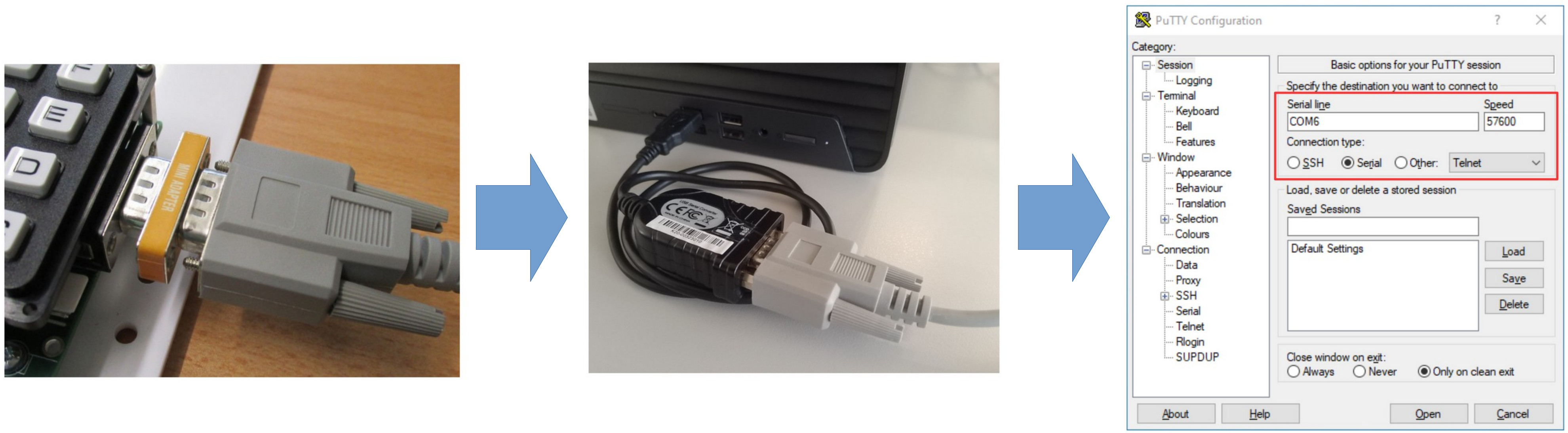

Figure 2 : Serial connectors, Putty (Windows), screen command (Linux)
Within the FPGA the serial port hardware i.e. the Universal Asynchronous Receiver Transmitter unit (UART) (Link) is mapped into the simpleCPU's memory map as shown in figure 3. The UART hardware has a fixed bit-rate, defined as a constant within its VHDL: 9600 to 57600 bps and no internal FIFO buffers i.e. it only has TX and RX registers. Therefore, its the monitor software's responsibility to ensure that as data is received it is moved into a software queue, otherwise the next character received will overwrite the last one. Similar for transmission of data, the monitor software has to check that the last character sent to the UART has been transmitted, otherwise it could overwrite/corrupt the current character being transmitted i.e. flow control is implemented in software. The serial port connector on the FPGA board is only wired up to the TX and RX pins, flow control pins such as RTS and CTS are not connected, a design choice to reduce hardware, save money, what could go wrong :).
Note, if you would like to know more about UARTs, digikey has a good article and VHDL implementation here: (Link).
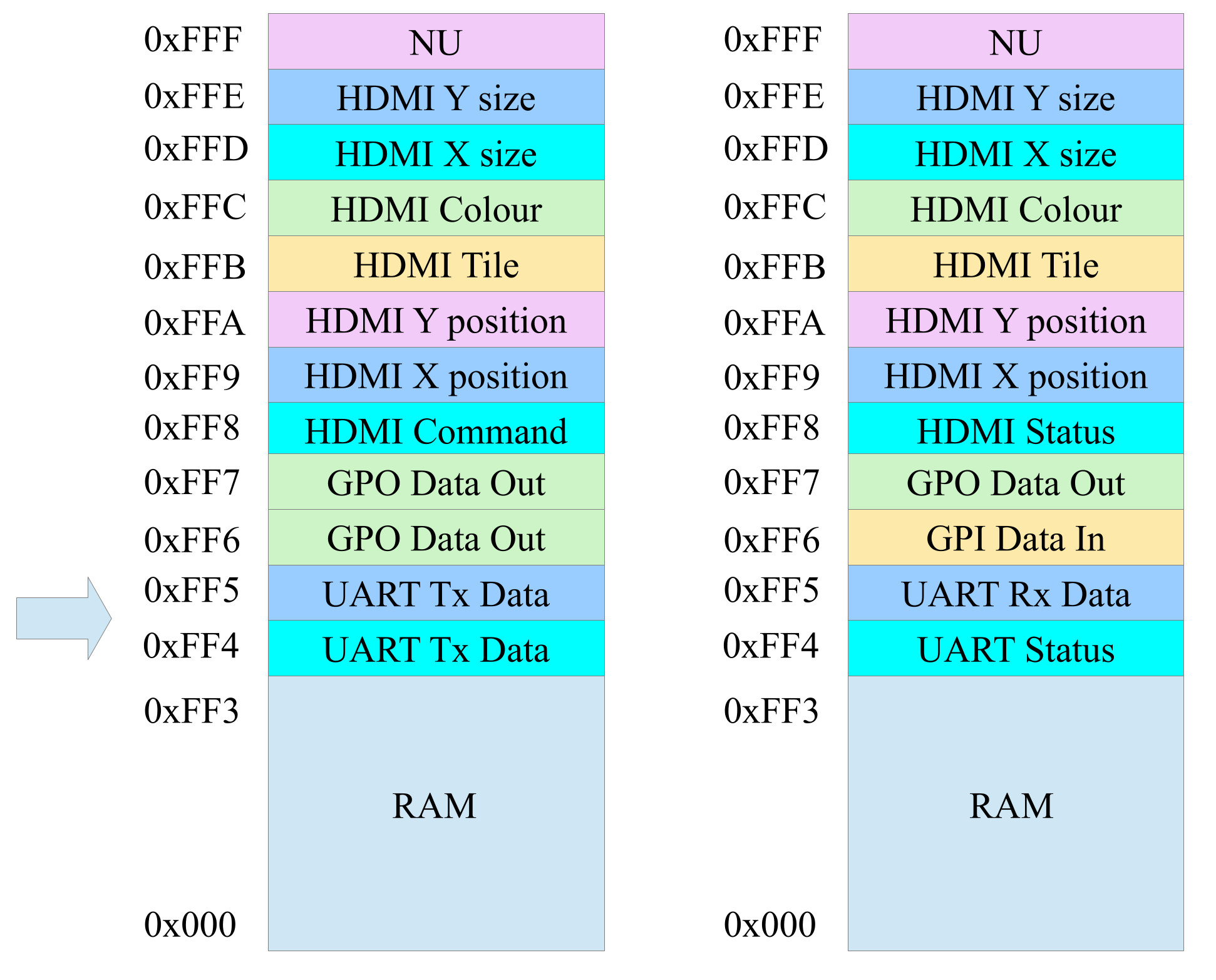
Figure 3 : Memory map
To replicate WozMon on the simpleCPU you first need to understand what commands were supported in this software and how these commands were used. Finding information about this code was relatively easy, in the land of retro computing its a historically significant piece of code, but finding detailed examples of how this code behaved for different combinations of commands, or error states was a little more tricky i.e. lots of contradicting statements regarding what it could and could not do. Yes, i could go through the original source code, but with any optimised software/hardware you sometimes never know what secret sauce was used i.e. what undocumented "feature" made the system behave the way it did. Also, it would be a lot of work :). Sooo, i decided to base my version of WozMon i.e. MikeMon, on the information obtained from this webpage: (Link). Also as the Apple-I was based on the 6502 there are some requirement differences, sooo MikeMon will not be an exact copy, some small changes with be needed for the simpleCPU implementation.
When running the monitor program it will display a "\" symbol as a prompt. I also decided to add a welcome banner, display "MikeMon", to show that the monitor code has started, or has been reset when an error occurs, as shown in figure 4. When a command is completed successfully, or when you just press the enter key, a new prompt "\" symbol is displayed. The user can now enter read, write or execute commands to manipulate memory, or run programs.
Note, i decided to keep the cursor on the same line as the "\" symbol, as you would see in a normal command-line terminal, in the original WozMon the cursor was moved below the "\" symbol when you entered a command.
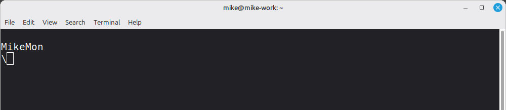
Figure 4 : MikeMon
To read data stored in a memory location you simply enter its address, then press the ENTER key, as shown in figure 5. To simplify coding the address must be specified in hex i.e. base-16. For the simpleCPU the range of addresses is 0x000 to 0xFFF i.e. the simpleCPU has a 12bit address bus. You do not need to enter the leading "0x", or all three digits e.g. 00A, 0A and A all represent the address 10 in decimal. If you were to enter more than three digits for an address only the last 3 digits are used e.g. 1234 would be treated as address 0x234, or 564 in decimal. Hex digits A, B, C, D, E and F must be capital letters, lower case letters will cause an error i.e. restart the monitor code. When complete a new prompt "\" symbol is displayed.
Note, you can use this three character limit to correct mistakes when typing e.g. 122123 will "overwrite" the incorrect address 122 with 123. Like the original WozMon you can press the BACKSPACE key to delete an entered char, however, like Wozmon this deletion is not displayed on the screen, it is only recorded internally in the code. If all else fails you can restart MikeMon by pressing the ESC key.
Read command examples
---------------------

4F                 # read single memory location, display data at address 0x4F or decimal 71.
4F 52 56           # read multiple memory locations, display data from address 0x4F, 0x52 and 0x56
.59                # read block of memory locations, display data from the last read address to address 0x59
4F.5F              # read block of memory locations, display data from address 0x4F to address 0x5F
4F.52 56 58.5A     # mix mode, block read, followed by a single read, followed by a block mode, any combinations allowed.
Note, a SPACE char separates the read commands. You can not have multiple SPACE chars in a row i.e. a space followed by a space, as after a SPACE char is received the monitor code is expecting a hex digit, a number. The end of a command is identified by either a SPACE char, or a ENTER char.
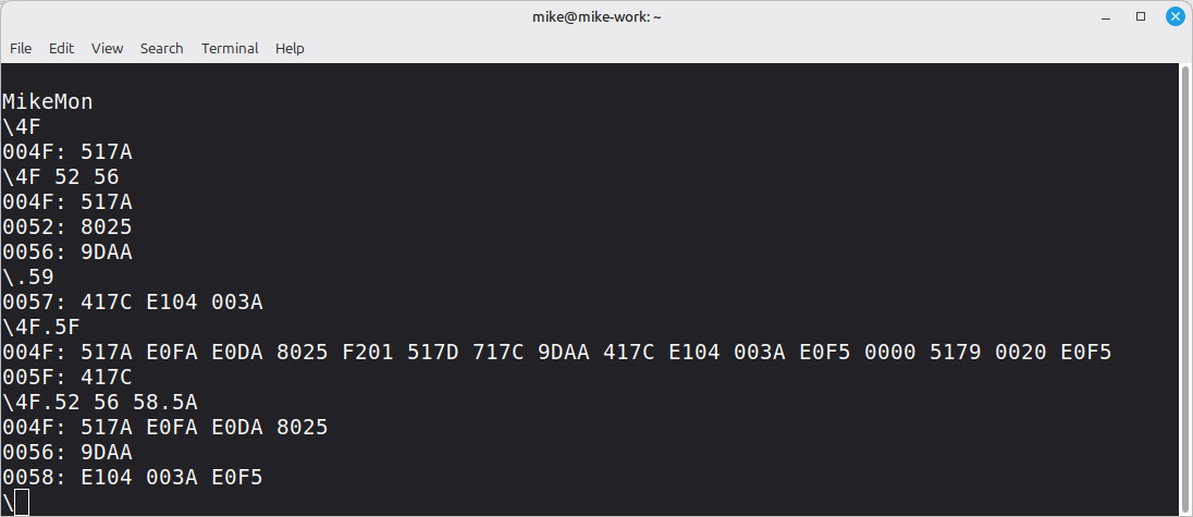
Figure 5 : read commands
A difference to WozMon is that data is displayed as 16bit values as the simpleCPU's memory is 16bits wide. When performing a block reads, values are displayed in lines of 16 words i.e. to prevent word wrap in the terminal. Each line starts with the address of the first data element in that row, as shown in figure 6.
Note, not quite sure of the rules when using the ".XXX" block read command i.e. what start address to use. I have seen different explanations, the way i have implemented it is that it start from the next unread memory location e.g. if you perform a read of address 60, then enter the command ".63", MikeMon will display the values of memory locations 61, 62 and 63, as you have already seen what is in memory location 60.
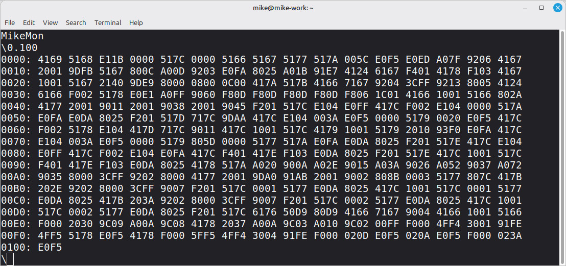
Figure 6 : block read command
To write data to a memory location you enter its address, then a COLON character, the data to be stored and then ENTER, as shown in figure 7. Again the address and data values must be specified in hex i.e. base-16, address range is 12bits: 0x000 to 0xFFF and data is 16bits: 0x0000 to 0xFFFF. Like the address you do not need to enter all four data digits e.g. 000A, 00A, 0A and A all represent the data 10 in decimal. To signal that the write or block write has been performed the previous value store in that address is first read and displayed i.e. displays the old value. When complete a new prompt "\" symbol is displayed.
Note, not sure why Wozmon read and displayed the old value when you do a write, i have kept this behaviour in for the moment, but may remove it. Also, not quite sure of the rules when using the ":" write command i.e. some examples have a SPACE char between the ":" and the data digits, others do not. I decided not to have a SPACE char i.e. "400:A" rather than "400: A", as its less to type and felt more inline with the "." read command.
Write examples
400:A0                        # write single memory location, memory location 0x400 is updated with the value 0x00A0
:A1                           # write single memory location, write data to the last write address+1
:A2 A3 A4                     # write block of memory locations, write data to the last write address+1, then to sequential memory locations
410:A0 A1 A2 A3 A4            # write block of memory locations, write data to sequential addresses M[410]=0xA0, M[411]=0xA1, M[412]=0xA2,
                              # M[413]=0xA3, M[414]=0xA4.
Note, again not quite sure of the rules when using the ":XXX" single or block write command i.e. what is the start address. Again the way i have implemented it is that it starts from the next memory location e.g. if you perform a write of address 60, then enter the command ":FF", MikeMon will write the value 0x00FF to memory location 61.
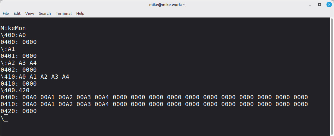
Figure 7 : write commands
The final command supported by WozMon is the run command: "R". To execute a program stored in memory the user enters the address of the first instruction, a "R" char and then ENTER. The the monitor code then jumps to that instruction and control of the UART and the processor switches to this program.
Run Example
100R            # jump to address 0x100 and execute instruction
To test if this command works correctly we need some code to run :). This can be anything e.g. 1 + 1, but to make this code visible via the serial port i decided to implement the classic "Hello World" test program, shown below. This program can be stored anywhere in free memory, sooo, a random choice of address 600, or 0x258 hex.
.addr 0
start:

.addr 600
uart_tx_string:
  load ra message_address
  move rb ra

uart_tx_string_loop:
  load ra (rb)                     # load  char
  and ra 0xFF
  jumpz uart_tx_string_exit        # exit if 0
  move rc ra

uart_tx_string_wait:
  load ra UART_STATUS              # test status
  and ra 0x04                      # VERSION-A
  jumpz uart_tx_string_wait

  move ra rc
  store ra UART_TX                 # tx ASCII char

  add rb 1                         # inc address
  jump uart_tx_string_loop         # repeat

uart_tx_string_exit:
  jump start

message_address:
  .data message

message:
  .data 0x0D    # CR
  .data 0x0A    # LF
  .data 0x48    # H
  .data 0x65    # e
  .data 0x6C    # l
  .data 0x6C    # l
  .data 0x6F    # o
  .data 0x20    # SPACE
  .data 0x57    # W
  .data 0x6F    # o
  .data 0x72    # r
  .data 0x6C    # l
  .data 0x64    # d
  .data 0x0D    # CR
  .data 0x0A    # LF
  .data 0x00    # NULL
This program can be assembled using the normal assembler which will produce an .asc file. This file format defines blocks of data on separated lines. Data values on a line are separated by a space. The number at the start of a line is the address in memory of the first data value, subsequent values are written to sequential addresses. The .asc file for the above program is:
0258 4266 F401 F102 30FF 9009 F801 4FF4 3004 91FE F201 5FF5 1401 825A 8000 0267 000D
0268 000A 0048 0065 006C 006C 006F 0020 0057 006F 0072 006C 0064 000D 000A 0000
To write this data to memory the user can manually enter these hex values using the monitor's single or block write commands, or they can using the python code below, you can download this file here: (convert-asc-2-txt.py).
import os
import sys

BLOCK_SIZE = 4  # Number of data values per line in output file

def process_asc_file(input_path, block_size):
    formatted_lines = []

    with open(input_path, 'r', encoding='ascii', errors='ignore') as file:
        for line in file:
            tokens = line.strip().split()
            if not tokens:
                continue

            base_addr_str = tokens[0]
            data_tokens = tokens[1:]

            try:
                base_addr = int(base_addr_str, 16)
            except ValueError:
                print("ERROR: could not convert HEX value")
                sys.exit(1)

            # If line has no data after address skip
            if not data_tokens:
                formatted_lines.append(f"{base_addr_str}:\r")
                continue

            for i in range(0, len(data_tokens), block_size):
                chunk = data_tokens[i:i + block_size]
                current_addr = base_addr + i
                addr = f"{current_addr:04X}"

                # Format: Address:data1 data2 data3 ... CR
                joined_data = " ".join(chunk)
                formatted_lines.append(f"{addr}:{joined_data}\r")

    return formatted_lines


def convert_file():
    if len(sys.argv) < 2:
        print("Usage: python3 convert-asc-2-txt.py ")
        sys.exit(1)

    input_file = sys.argv[1]

    if not os.path.exists(input_file):
        print(f"ERROR: Input file '{input_file}' not found.")
        sys.exit(1)

    file_root, _ = os.path.splitext(input_file)
    output_file = f"{file_root}.txt"

    try:
        lines = process_asc_file(input_file, BLOCK_SIZE)

        with open(output_file, 'wb') as file:
            for line in lines:
                file.write(line.encode('ascii'))

        print(f"Converted '{input_file}' to '{output_file}'")
        print(f"Number of lines: {len(lines)}")

    except Exception as e:
        print(f"ERROR: An error occurred: {e}")


if __name__ == '__main__':
    convert_file()
This code produces the data below, the user can then cut and paste this into the terminal.
0258:4266 F401 F102 30FF
025C:9009 F801 4FF4 3004
0260:91FE F201 5FF5 1401
0264:825A 8000 0267 000D
0268:000A 0048 0065 006C
026C:006C 006F 0020 0057
0270:006F 0072 006C 0064
0274:000D 000A 0000
This is very much a pre-release version, a work in progress, buyer beware :). Listing below, you can download this file here: (mikemon_v1.asm). Unfortunately the lack of flow control on the UART has come back to bite me :(. From a normal serial terminal e.g. Putty or screen, with a human "user" all works fine, as the processor has milliseconds worth of delays between key presses to receive and send characters. However, if you cut-&-paste valid write commands into the serial terminal, the program will blast this data down the serial line as fast as possible i.e. no delays between characters, which will cause serial data to be dropped i.e. characters transmitted from the PC to be missed, as shown in figure 8. This screen shot shows what happens when the "Hello World" test program is cut and pasted into a screen terminal :(
Note, the reason for cut-&-paste into the serial terminal was to allow the user to upload a program i.e. use multiple block write command, rather than having to manually type this data. Once the program had been written into memory the user could then run this program using the "R" command.
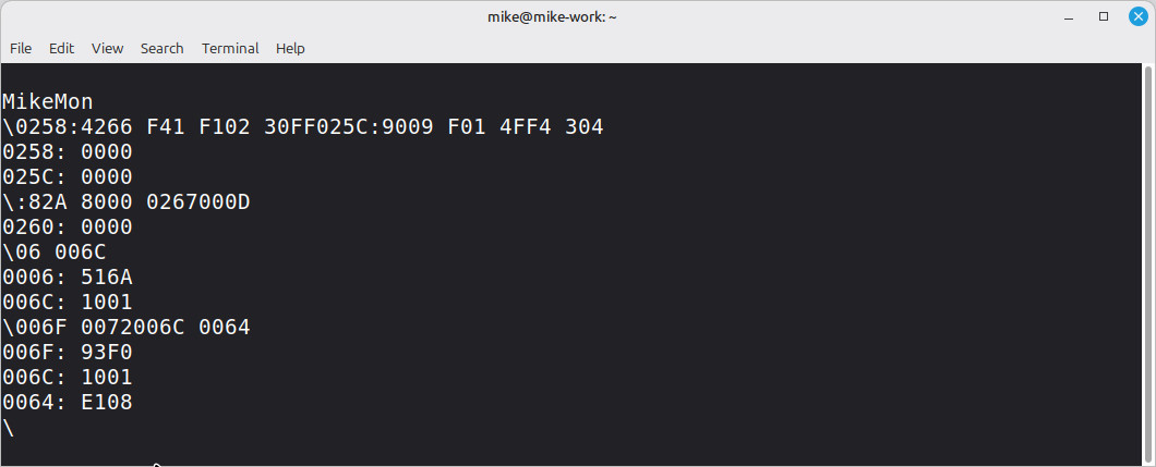
Figure 8 : error produced when cut and pasting test code
To understand what the issue is consider the block write command below:
MISSED -                                                    X X X X X X X  X X X X X
RX     - 0 1 F 4 : 0 0 0 1 SP 0 0 0 2 0 0 0 3 SP 0 0 0 4 CR
TX     -   0 1 F 4 : 0 0 0 1 SP 0 0 0 2 0 0 0 3 SP 0 0 0 4 CR 0 1 F 4 : SP 0 0 0 0 CR
Each received character is echoed back to the serial terminal by the monitor code, so that the user can see what they are typing. From a timing point of view this is ok, as you have one char in and one char out, BUT each time a Carriage Return (CR) character is sent the monitor will also send back to the terminal the old value of the first address written to i.e. in the above example 01F4:0000. Thats 11 characters (including CR), sooo whilst this is being transmitted to the PC the monitor code can not receive the next block of write commands i.e. tx code is blocking, it waits until the string "01F4:0000" has been transmitted :(.
##############
# MikeMon v1 #
##############
##############
# MEMORY MAP #
##############
# ADDR WR RD
# 0xFFE HDMI_Y_SIZE HDMI_Y_SIZE
# 0xFFD HDMI_X_SIZE HDMI_X_SIZE
# 0xFFC HDMI_COLOUR HDMI_COLOUR
# 0xFFB HDMI_TILE HDMI_TILE
# 0xFFA HDMI_Y_POS HDMI_Y_POS
# 0xFF9 HDMI_X_POS HDMI_X_POS
# 0xFF8 HDMI_COMMAND HDMI_COMMAND
# 0xFF8 HDMI_STATUS HDMI_STATUS
# 0xFF7 GPO GPO
# 0xFF6 GPO GPI
# 0xFF5 UART TX DATA UART RX DATA
# 0xFF4 UART TX DATA UART STATUS
# 0xFF3 MEM RAM RAM
# ... ... ...
# 0x000 MEM RAM RAM
##################
# UART REGISTERS #
##################
# TX : B7 - B0 data
# RX : B7 - B0 data
# STATUS REGISTER VERSION-A
# -------------------------
# B7 : NU
# B6 : NU
# B5 : NU
# B4 : NU
# B3 : NU
# B2 : TX Idle
# B1 : RX Idle
# B0 : RX Valid
###############
# ASCII CODES #
###############
# Dec Hex Char Dec Hex Char Dec Hex Char Dec Hex Char
# ------------ ------------ ------------ ------------
# 0 00 NUL (null) 32 20 SPACE 64 40 @ 96 60 `
# 1 01 SOH (start of heading) 33 21 ! 65 41 A 97 61 a
# 2 02 STX (start of text) 34 22 " 66 42 B 98 62 b
# 3 03 ETX (end of text) 35 23 # 67 43 C 99 63 c
# 4 04 EOT (end of transmission) 36 24 $ 68 44 D 100 64 d
# 5 05 ENQ (enquiry) 37 25 % 69 45 E 101 65 e
# 6 06 ACK (acknowledge) 38 26 & 70 46 F 102 66 f
# 7 07 BEL (bell) 39 27 ' 71 47 G 103 67 g
# 8 08 BS (backspace) 40 28 ( 72 48 H 104 68 h
# 9 09 TAB (horizontal tab) 41 29 ) 73 49 I 105 69 i
# 10 0A LF (NL line feed, new line) 42 2A * 74 4A J 106 6A j
# 11 0B VT (vertical tab) 43 2B + 75 4B K 107 6B k
# 12 0C FF (NP form feed, new page) 44 2C , 76 4C L 108 6C l
# 13 0D CR (carriage return) 45 2D - 77 4D M 109 6D m
# 14 0E SO (shift out) 46 2E . 78 4E N 110 6E n
# 15 0F SI (shift in) 47 2F / 79 4F O 111 6F o
# 16 10 DLE (data link escape) 48 30 0 80 50 P 112 70 p
# 17 11 DC1 (device control 1) 49 31 1 81 51 Q 113 71 q
# 18 12 DC2 (device control 2) 50 32 2 82 52 R 114 72 r
# 19 13 DC3 (device control 3) 51 33 3 83 53 S 115 73 s
# 20 14 DC4 (device control 4) 52 34 4 84 54 T 116 74 t
# 21 15 NAK (negative acknowledge) 53 35 5 85 55 U 117 75 u
# 22 16 SYN (synchronous idle) 54 36 6 86 56 V 118 76 v
# 23 17 ETB (end of trans. block) 55 37 7 87 57 W 119 77 w
# 24 18 CAN (cancel) 56 38 8 88 58 X 120 78 x
# 25 19 EM (end of medium) 57 39 9 89 59 Y 121 79 y
# 26 1A SUB (substitute) 58 3A : 90 5A Z 122 7A z
# 27 1B ESC (escape) 59 3B ; 91 5B [ 123 7B {
# 28 1C FS (file separator) 60 3C < 92 5C \ 124 7C |
# 29 1D GS (group separator) 61 3D = 93 5D ] 125 7D }
# 30 1E RS (record separator) 62 3E > 94 5E ^ 126 7E ~
# 31 1F US (unit separator) 63 3F ? 95 5F _ 127 7F DEL
#####################
# TERMINAL COMMANDS #
#####################
# Common serial port speeds
# Bit rate (bit/s) Time per bit (μs) Common applications
# ---------------- ----------------- -------------------
# 75 13333.3
# 110 9090.9 Bell 101 modem
# 134.5 7434.9
# 150 6666.6
# 300 3333.3 Bell 103 modem or V.21 modem
# 600 1666.7
# 1,200 833.3 Bell 202, Bell 212A, or V.22 modem
# 1,800 555.6
# 2,400 416.7 V.22bis modem
# 4,800 208.3 V.27ter modem
# 7,200 138.9
# 9,600 104.2 V.32 modem
# 14,400 69.4 V.32bis modem
# 19,200 52.1
# 31,250 32 MIDI port
# 38,400 26.0
# 56,000 17.9 V.90/V.92 modem
# 57,600 17.4 V.32bis modem with V.42bis compression ****
# 76,800 13.0 BACnet MS/TP networks[20]
# 115,200 8.68 V.34 modem with V.42bis compression,
# low cost serial V.90/V.92 modem with V.42bis or V.44 compression
# screen /dev/ttyS0 19200,cs8
# screen /dev/ttyUSB0 57600
# Screen Command Task
# -------------- ----
# Ctrl+a c Create new window
# Ctrl+a k Kill the current window / session
# Ctrl+a w List all windows
# Ctrl+a 0-9 Go to a window numbered 0 9, use Ctrl+a w to see number
# Ctrl+a Ctrl+a Toggle / switch between the current and previous window
# Ctrl+a S Split terminal horizontally into regions and press Ctrl+a c to create new window there
# Ctrl+a :resize Resize region
# Ctrl+a :fit Fit screen size to new terminal size. You can also hit Ctrl+a F for the the same task
# Ctrl+a :remove Remove / delete region. You can also hit Ctrl+a X for the same taks
# Ctrl+a tab Move to next region
# Ctrl+a D (Shift-d) Power detach and logout
# Ctrl+a d Detach but keep shell window open
# Ctrl-a Ctrl-\ Quit screen
# Ctrl-a ? Display help screen i.e. display a list of commands
# Backspace allowed to delete entered char, but display is not updated
# Escape restarts
# Monitor Commands
# ----------------
# Read examples
# 4F
# .55
# 4F 52 56
# 4F.5F
# 4F.52 56 58.5A
# Write examples
# 30:A0
# :A1 A2 A3 A4 A5
# 30:A0 A1 A2 A3 A4 A5
# Run
# 100 R
# Main Program
# ------------
start:
load ra welcome_address # display welcome message
store ra string_pointer
call uart_tx_string
move ra 0
store ra address
restart:
move ra 0 # reset buffer index
store ra buffer_rd_index
store ra buffer_wr_index
store ra mode
store ra current_command
move ra 0x5C # display prompt "\"
call uart_tx
# 7F DEL 0
# 0D CR 6
# 1B ESC 13
get_CHAR:
call uart_rx # wait for CHAR
cmp ra 0x7F # DEL?
jumpnz get_CHAR_test_cr
load ra buffer_wr_index # yes, decrement write index
sub ra 1
jumpn get_CHAR
store ra buffer_wr_index
jump get_CHAR
get_CHAR_test_cr:
cmp ra 0x0D # CR?
jumpnz get_CHAR_test_esc
call uart_tx_cr_lf
jump process_BUF # yes, process buffer
get_CHAR_test_esc:
cmp ra 0x1B # ESC?
jumpz start # yes, error start
get_CHAR_test_line_feed:
cmp ra 0x0A # LF?
jumpz get_CHAR # yes, ignore
get_CHAR_buffer:
load ra buffer_address # no, store in buffer, must be in first 255 addr
addm ra buffer_wr_index # calc buffer address
move rb ra
load ra tmp # reload RX data
store ra (rb) # store in buffer
load ra buffer_wr_index # increment index
add ra 1
store ra buffer_wr_index
subu ra 64 # exceeded buf size 0-63?
jumpn get_CHAR # no, repeat
jump start # yes, error restart
# when CR pressed process data, buffer_wr_index points to last empty space
process_BUF:
move rc 0 # rc = address
move rd 0 # rd = digit count
load ra current_command
store ra previous_command # log command to detect duplicates
load ra buffer_rd_index # get read index
digit_loop:
subm ra buffer_wr_index # does read index = write index = empty space?
jumpnz digit_read_char # no, read char
and rd 0xFF
jumpnz decode_NUM # digits entered decode
jump restart # no digits entered restart
digit_read_char:
load ra buffer_address
addm ra buffer_rd_index # generate read pointer
load ra (ra) # read buffer
store ra tmp
call test_digit # is char a hex digit
cmp ra 0xFF
jumpz decode_CMD # not a digit, decode
asl rc # move hex digit up
asl rc
asl rc
asl rc
add rc ra # add new digit
add rd 1 # increment number digit count
digit_inc_index:
load ra buffer_rd_index # inc read pointer
add ra 1
store ra buffer_rd_index
jump digit_loop # repeat
decode_NUM:
# 0 = read
# 1 = multi read
# 2 = write
# 3 = multi write
load ra mode
sub ra 1
jumpz decode_NUM_multiple_read
sub ra 1
jumpz decode_NUM_single_write
sub ra 1
jumpz decode_NUM_multiple_write
decode_NUM_single_read:
move ra rc # save generated address
store ra address
call uart_tx_hex # text data
call uart_tx_colon_space # tx address
load ra address
load ra (ra) # read data at address
call uart_tx_hex # text data
move ra 0
#store ra mode
store ra current_command
call uart_tx_cr_lf
call inc_rd_index # inc read index
jump process_BUF # continue
decode_NUM_multiple_read:
move ra rc # save generated address
store ra max_address
subm ra address # is address >= max error
jumpn start
load ra address
call uart_tx_hex # tx address
move ra 0x3A # tx colon
call uart_tx
move ra 0 # line length count
store ra count
decode_NUM_multiple_read_loop:
move ra 0x20 # tx space
call uart_tx
load ra address
load ra (ra) # read data at address
store ra tmp
call uart_tx_hex # tx data
load ra max_address # is address > max_address
subm ra address
jumpz decode_NUM_multiple_read_exit
load ra address # inc address
add ra 1
store ra address
load ra count # max line length?
add ra 1
store ra count
sub ra 16
jumpnz decode_NUM_multiple_read_loop
call uart_tx_cr_lf # yes, newline
load ra address
call uart_tx_hex # tx address
move ra 0x3A # tx colon
call uart_tx
move ra 0 # reset line count
store ra count
jump decode_NUM_multiple_read_loop
decode_NUM_multiple_read_exit:
move ra 0
store ra mode
store ra current_command
call uart_tx_cr_lf
call inc_rd_index
jump process_BUF # continue
decode_NUM_single_write:
move ra rc # save generated data
store ra data
load ra address
call uart_tx_hex # text data
call uart_tx_colon_space # tx address
load ra address
load ra (ra) # read data at address
call uart_tx_hex # text data
call uart_tx_cr_lf
load ra address # read address
move rb ra
load ra data # read data
store ra (rb) # write data
call inc_rd_index
jump process_BUF # continue
decode_NUM_multiple_write:
move ra rc # save generated data
store ra data
load ra address # read address
add ra 1 # inc
store ra address
move rb ra
load ra data # read data
store ra (rb)
call inc_rd_index #
jump process_BUF # continue
# 20 SP
# 2E .
# 3A :
# 52 R
# 72 r
decode_CMD:
load ra tmp # read char
store ra current_command
cmp ra 0x20
jumpz decode_CMD_space # space
cmp ra 0x2E
jumpz decode_CMD_dot # full stop = read
cmp ra 0x3A
jumpz decode_CMD_colon # colon = write
cmp ra 0x52
jumpz decode_CMD_run # R = run
cmp ra 0x72
jumpz decode_CMD_run # r = run
jump start # error, restart
decode_CMD_space:
and rd 0xFF # was there a number
jumpnz decode_CMD_space_update
jump start # error, restart
decode_CMD_space_update:
load ra mode
sub ra 1
jumpn decode_NUM_single_read # if 0 mode read
jumpz decode_NUM_multiple_read # if 1 mode multiple read
sub ra 1
jumpz decode_CMD_space_update_1 # if 2 mode write
jump decode_NUM_multiple_write # if 3 mode multiple write
decode_CMD_space_update_1:
move ra 3 # update mode to write multiple
store ra mode
jump decode_NUM_single_write
decode_CMD_dot:
load ra previous_command
sub ra 0x2E # was previous command a dot
jumpnz decode_CMD_dot_update
jump start # error, restart
decode_CMD_dot_update:
and rd 0xFF # was there a number
jumpz decode_CMD_dot_update_1
move ra rc # save generated address
store ra address
move ra 1 # flag read multiple
store ra mode
call inc_rd_index
jump process_BUF # continue
decode_CMD_dot_update_1:
load ra address # no number, inc old address
add ra 1
store ra address
move ra 1 # flag read multiple
store ra mode
call inc_rd_index
jump process_BUF # continue
decode_CMD_colon:
load ra previous_command # was previous command a colon
sub ra 0x3A
jumpnz decode_CMD_colon_update
jump start # error, restart
decode_CMD_colon_update:
and rd 0xFF # was there a number?
jumpz decode_CMD_colon_update_1
move ra rc # save generated address
store ra address
move ra 2 # flag as write
store ra mode
call inc_rd_index
jump process_BUF # continue
decode_CMD_colon_update_1:
load ra address # no, increment address
add ra 1
store ra address
move ra 2 # flag as write
store ra mode
call inc_rd_index
jump process_BUF # continue
decode_CMD_run:
move ra rc # save generated address
store ra address
addm ra const_0x8000 # turn into a JUMP instruction
store ra decode_CMD_run_go # overwrite instruction
decode_CMD_run_go:
jump decode_CMD_run_go # run code
###############
# SUBROUTINES #
###############
# increment read index
# --------------------
inc_rd_index:
load ra buffer_rd_index
subm ra buffer_wr_index # does read index = write index = empty space?
jumpz inc_rd_index_exit # exit
load ra buffer_rd_index # inc read index
add ra 1
store ra buffer_rd_index
inc_rd_index_exit:
ret # exit
# Test if char is a digit
# -----------------------
# 0 to 9 = 0x30 to 0x39
# A to F = 0x41 to 0x46
test_digit:
sub ra 0x30 # Shift ASCII digits down
jumpn test_digit_err # < '0' -> invalid
cmp ra 10
jumpn test_digit_exit # '0'..'9' -> valid (0..9)
load ra tmp
sub ra 0x37 # Shift ASCII hex upper ('A' = 0x41 -> 10)
cmp ra 10
jumpn test_digit_err # < 'A' -> invalid
cmp ra 16
jumpn test_digit_exit # 'A'..'F' -> valid (10..15)
test_digit_err:
move ra 0xFF # Not a valid hex char
test_digit_exit:
ret
###########################
# SERIAL PORT SUBROUTINES #
###########################
# STATUS REGISTER VERSION-A
# -------------------------
# B7 : NU 128
# B6 : NU 64
# B5 : NU 32
# B4 : NU 16
# B3 : NU 8
# B2 : TX Idle 4
# B1 : RX Idle 2
# B0 : RX Valid 1
# RX Char
# -------
uart_rx:
load ra UART_STATUS # test status
and ra 0x01 #
jumpz uart_rx
load ra UART_RX
store ra tmp
call uart_tx # echo recieved char
load ra tmp # reload
ret
# TX Char
# -------
uart_tx:
store ra char
uart_tx_wait:
load ra UART_STATUS # test status
and ra 0x04 #
jumpz uart_tx_wait
load ra char
store ra UART_TX # tx ASCII char in RA
ret
# TX CR LF
# --------
uart_tx_cr_lf:
moveu ra 0x0D # tx CR
call uart_tx
moveu ra 0x0A # tx LF
call uart_tx
ret
# TX COLON SPACE
# --------------
uart_tx_colon_space:
moveu ra 0x3A # tx COLON
call uart_tx
moveu ra 0x20 # tx SPACE
call uart_tx
ret
# TX Hex 16bit
# ------------
uart_tx_hex:
store ra tmp # buffer char
xchg ra
asr ra
asr ra
asr ra
asr ra # tx X000
call print_nibble
load ra tmp
xchg ra # tx 0X00
call print_nibble
load ra tmp # tx 00X0
asr ra
asr ra
asr ra
asr ra
call print_nibble
load ra tmp # tx 000X
print_nibble:
and ra 0x0F
add ra 0x30 # Convert 0-9 to ASCII '0'-'9'
cmp ra 0x3A
jumpn print_nibble_send
add ra 0x07 # Convert 10-15 to ASCII 'A'-'F'
print_nibble_send:
jump uart_tx # Send character
# TX String (must terminate with a \0)
# ------------------------------------
uart_tx_string:
load ra string_pointer
move rb ra
uart_tx_string_loop:
load ra (rb) # load char
and ra 0xFF
jumpz uart_tx_string_exit # exit if 0
call uart_tx # tx
add rb 1 # inc address
jump uart_tx_string_loop # repeat
uart_tx_string_exit:
ret
########
# DATA #
########
buffer_address:
.data buffer
buffer:
space(64)
buffer_rd_index:
.data 0
buffer_wr_index:
.data 0
string_pointer:
.data 0
# ------------------
# - Welcome string -
# ------------------
welcome_address:
.data welcome
welcome:
.data 0x0A # LF
.data 0x0D # CR
.data 0x4D # M
.data 0x69 # i
.data 0x6B # k
.data 0x65 # e
.data 0x4D # M
.data 0x6F # o
.data 0x6E # n
.data 0x0A # LF
.data 0x0D # CR
.data 0x00 # NULL
# Constants
# ---------
const_0x8000:
.data 0x8000
# Variables
# ---------
# 0 = normal
# 1 = prev read
# 2 = prev write
# 3 = prev write space
mode:
.data 0
tmp:
.data 0
count:
number:
.data 0
current_command:
.data 0
previous_command:
.data 0
address:
.data 0
max_address:
.data 0
data:
.data 0
char:
.data 0
To prevent commands / characters from the PC from being dropped we could consider a number of different solutions, or a combination of these:
PC          FPGA
TX   --->   RX
RX   <---   TX
RTS  --->   CTS
CTS  <---   RTS
Sooo, to move to a non-blocking solution the software needs a TX and RX buffer (queue). These can be implemented in software using the code below:
Note, TX buffer code not listed as its the same as the RX code. Should really rename the variable "tmp" to "char".
###############
# SUBROUTINES #
###############

# RX buffer write
# ---------------
# Returns RA = 0 on success, 0xFFFF if full

rx_buffer_write:
  load ra rx_buffer_wr_index       # calc next wr_index
  add ra 1
  and ra 0x3F
  subm ra rx_buffer_rd_index       # Does wr_index + 1 = rd_index?
  jumpz rx_buffer_write_full       # yes, buffer is full

  load ra rx_buffer_wr_index
  addm ra rx_buffer_address
  move rb ra
  load ra tmp
  store ra (rb)

  load ra rx_buffer_wr_index       # update wr_index
  add ra 1
  and ra 0x3F
  store ra rx_buffer_wr_index
  move ra 0                        # Success
  ret

rx_buffer_write_full:
  move ra 0xFF                     # Buffer full
  ret

# RX buffer read
# --------------
# Returns RA = Data, or 0xFFFF if empty

rx_buffer_read:
  load ra rx_buffer_wr_index
  subm ra rx_buffer_rd_index       # Does wr_index = rd_index?
  jumpz rx_buffer_read_empty       # yes, buffer is empty

  load ra rx_buffer_rd_index       # read value from buffer
  addm ra rx_buffer_address
  move rb ra
  load ra (rb)
  store ra tmp

  load ra rx_buffer_rd_index       # update rd_index
  add ra 1
  and ra 0x3F
  store ra rx_buffer_rd_index

  load ra tmp                      # Return character
  ret

rx_buffer_read_empty:
  move ra 0xFF                     # Buffer empty
  ret

# TX buffer write
# ---------------
# Returns RA = 0 on success, 0xFFFF if full

tx_buffer_write:
  ...

# TX buffer read
# --------------
# Returns RA = Data, or 0xFFFF if empty

tx_buffer_read:
  ...

########
# DATA #
########

rx_buffer_rd_index:
  .data 0

rx_buffer_wr_index:
  .data 0

rx_buffer_address:
  .data rx_buffer

rx_buffer:
  space(64)

tx_buffer_rd_index:
  .data 0

tx_buffer_wr_index:
  .data 0

tx_buffer_address:
  .data tx_buffer

tx_buffer:
  space(64)
This code implements a 63 byte buffer, a circular buffer accessed using rd_index and wr_index variables. when reading data if the rd_index = the wr_index the buffer is empty, when writing data if wr_index+1 = rd_index the buffer is full. The calling software can see if these read or write operations were successful via the returned value of RA, 0xFFFF = -1 = fail, 0 = pass. In addition to this the uart RX and TX subroutines need to be updated:
# RX Char
# -------
# Returns RA = Data, or 0xFFFF if no valid

uart_rx:
  load ra UART_STATUS              # test status
  and ra 0x01                      # VERSION-A
  jumpz uart_rx_empty

  load ra UART_RX
  store ra tmp                     # Valid
  ret

uart_rx_empty:
  move ra 0xFF                     # Not Valid
  ret

# TX Char
# -------

uart_tx:
  load ra tmp
  store ra UART_TX                 # tx ASCII char
  ret

# Returns RA = 0 if idle, or 0xFFFF if busy

uart_tx_ready:
  load ra UART_STATUS              # test status
  and ra 0x04                      # VERSION-A
  jumpnz uart_tx_ready_pass

uart_tx_ready_fail:
  move ra 0xFF                     # Fail
  ret

uart_tx_ready_pass:
  move ra 0                        # Pass
  ret
Like the buffer subroutines the return value in RA tells the calling code if this request was successful e.g. if uart_rx returns 0xFFFF then no RX character is available. Using these returned values the main program can be updated, as shown below. The remaining code is basically the same.
Note, not saying that MikeMon_v1 was hacked together, but i do confess this approach does improve the structure of the program, i.e. moves functionality into a single subroutines, rather than being distributed across the program :).
rx_CHAR:
  call uart_rx
  cmp ra 0xFF                      # test if CHAR valid
  jumpz tx_CHAR                    # not valid, transmit buffered char

  cmp ra 0x7F			           # DEL?
  jumpnz rx_CHAR_test_cr

  load ra rx_buffer_wr_index       # yes, is RX buffer empty?
  subm ra rx_buffer_rd_index       #
  jumpz tx_CHAR                    # yes, skip

  load ra rx_buffer_wr_index       # decrement rx_buffer_wr_index
  sub ra 1
  and ra 0x3F
  store ra rx_buffer_wr_index
  jump tx_CHAR

rx_CHAR_test_cr:
  cmp ra 0x0D			           # CR?
  jumpnz rx_CHAR_test_esc

  call uart_tx_lf
  call uart_tx_cr

  jump process_BUF                 # yes, process buffer

rx_CHAR_test_esc:
  cmp ra 0x1B			           # ESC?
  jumpz start                      # yes, error start

rx_CHAR_test_line_feed:
  cmp ra 0x0A			           # LF?
  jumpz tx_CHAR                    # yes, ignore

rx_CHAR_buffer:
  call rx_buffer_write             # write RX char to RX buffer
  cmp ra 0xFF
  jumpz start                      # error, rx buffer was full

  call tx_buffer_write             # echo char, write RX char to TX buffer
  cmp ra 0xFF
  jumpz start                      # error, rx buffer was full

tx_CHAR:
  call uart_tx_ready               # is uart TX ready
  cmp ra 0xFF
  jumpz rx_CHAR                    # no, skip

  call tx_buffer_read
  cmp ra 0xFF                      # is there data to TX
  jumpz rx_CHAR                    # no, skip
  call uart_tx
  jump rx_CHAR
Note, did have to make a couple of changes, the first was to the MikeMon read command. When reading blocks of data from memory the 63 byte TX buffer will soon be filled. The original thought of dropping data that did not fit into the TX buffer stopped this functionality working, sooo, if the monitor is in single or block reads it will block on a TX buffer full i.e. wait for data to be transmitted. If performing single or block writes it does not, it priorities writing data to the RX buffer. You can download a copy of this code here: (mikemon_v2.asm).
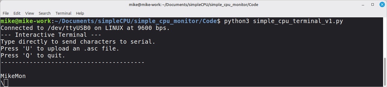
Figure 9 : simple_cpu_terminal_v1
MikeMon version 2 works fine, you can cut and paste text into the terminal and this will be written to memory i.e. it does allow a user to upload and run a program. However, the text echoed back to the screen will be wrong i.e. TX characters will be dropped when the TX buffer becomes full. An alternative solution is to add a delay after each character, mimic a person typing, give the MikeMon code time to echo back the serial data. This delay can be defined in Putty and the Linux screen command, but is a bit of a pain to do each time. Also, adding a delay does slow down the upload of code, but as we are typically only talking about a couple of KBs the delay is seconds, so not really an issue.
An alternative solution is to ask Gemini to write a python program to replace these serial terminals, create the all new and improved: simple_cpu_terminal. This python program adds a 10ms delay after each character, thus removing the flow control issues, allowing both MikeMon version 1 and 2 to function correctly, as shown in figure 10. You can download this python file here: (simple_cpu_terminal_v1.py).
Note, there is a small bug with regards the ESC key, this still works but the first "M" in "MikeMon" does is not displayed, not sure why, maybe something to do with ANSI ESC sequences, but apart from the all is fine.
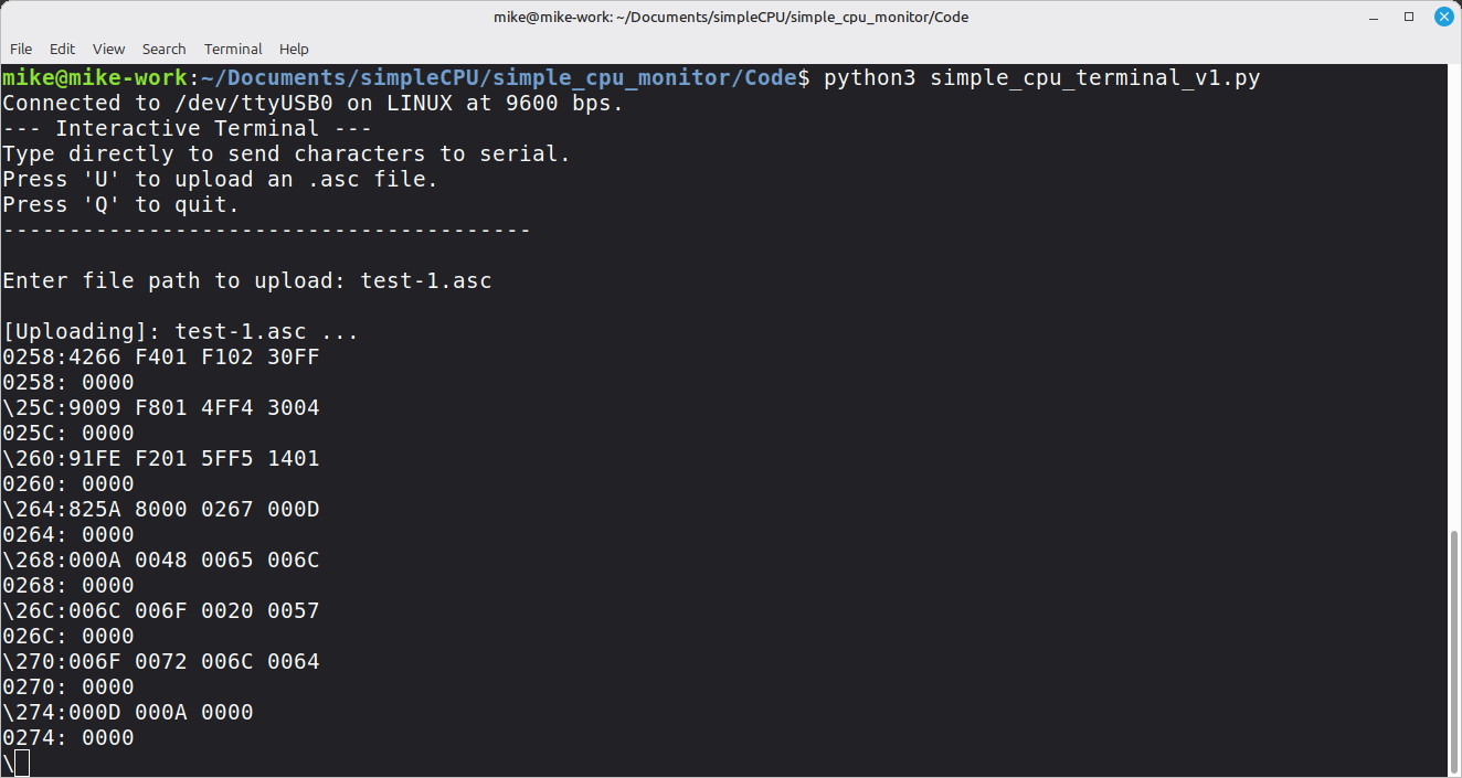
Figure 10 : simple_cpu_terminal upload
MikeMon version 2 works fine, but it does need TX and RX buffers implemented in software, thats 128 bytes of memory + code. Now that may not sound a lot, but when you only have 4096 bytes to start with, that a reasonable chuck. Sooo, an alternative to implementing these FIFO buffer in CPU memory is to implement them in hardware. Therefore, MikeMon version 3 is a software and hardware improvement i.e. an UART update, replacing its TX and RX registers with hardware based FIFOs. This frees up CPU memory by removing the code and data needed to implement these software queues, allowing larger games to be uploaded.
WORK IN PROGRESS
When implement the MikeMon code i needed to test the interaction between software and hardware i.e. MikeMon and the UART. So of this testing could be done on the FPGA, but when you are trying to understand where a bug is you need to look at how registers / variables are being updated. To do this i used the techniques described here: (Lnk), but also need to TX and RX serial data inside an ISim simulation. To do this i used some simple behavioural VHDL components / processes, that model this behaviour i.e. this type of VHDL can not be synthesised into hardware, simulation only.
-------------------
-- 8N1 Serial RX --
-------------------

library ieee;
use ieee.std_logic_1164.all;
use ieee.numeric_std.all;

entity uart_data_display is
  generic (
    BAUD_RATE : integer := 9600 );
  port (
    ser_in    : in  std_logic;
    data_out  : out std_logic_vector(7 downto 0) := (others => '0');
    valid_out : out std_logic                    := '0' );
end uart_data_display;

architecture uart_data_display_arch of uart_data_display is
  constant BIT_PERIOD : time := 1 sec / BAUD_RATE;

begin

  uart_monitor : process
    variable rx_shift : std_logic_vector(7 downto 0);
  begin
    valid_out <= '0';

    -- 1. Wait for falling edge of the Start Bit
    wait until falling_edge(ser_in);

    -- 2. Delay to mid-bit position to verify Start Bit = 0
    wait for BIT_PERIOD / 2;

    if ser_in = '0'
    then
      -- 3. Align to first data bit center
      wait for BIT_PERIOD;

      -- 4. Read 8 Data Bits (LSB first)
      for i in 0 to 7
      loop
        rx_shift(i) := ser_in;
        wait for BIT_PERIOD;
      end loop;

      -- 5. Stop Bit duration sample
      data_out  <= rx_shift;
      valid_out <= '1';
      wait for BIT_PERIOD;
    end if;
  end process;

end uart_data_display_arch;
-------------------
-- 8N1 Serial TX --
-------------------

library ieee;
use ieee.std_logic_1164.all;
use ieee.numeric_std.all;
use std.textio.all;

entity uart_data_source is
  generic (
    BAUD_RATE : integer := 9600;
    FILE_PATH : string  := "input.txt" );
  port (
    start   : in  std_logic;
    busy    : out std_logic := '0';
    ser_out : out std_logic := '1' );
end uart_data_source;

architecture uart_data_source_arch of uart_data_source is
  constant BIT_PERIOD : time := 1 sec / BAUD_RATE;

begin

  uart_sim: process
    file input_file       : text;
    variable line_buf     : line;
    variable char_val     : character;
    variable char_code    : integer;
    variable data_byte    : std_logic_vector(7 downto 0);
    variable read_success : boolean;

  begin
    ser_out <= '1';
    busy    <= '0';

    -- Wait for start signal, user signal, controlled from TB
    wait until rising_edge(start);

    busy <= '1';
    file_open(input_file, FILE_PATH, read_mode);

    -- Read text file line by line
    while not endfile(input_file)
    loop
      readline(input_file, line_buf);

      -- Process each character in line
      while line_buf'length > 0
      loop
        read(line_buf, char_val, read_success);
        if read_success
        then
          -- Convert character to 8-bit vector
          char_code := character'pos(char_val);
          data_byte := std_logic_vector(to_unsigned(char_code, 8));

          -- 1. START BIT
          ser_out <= '0';
          wait for BIT_PERIOD;

          -- 2. DATA BITS, 8 bits, LSB first
          for i in 0 to 7
          loop
            ser_out <= data_byte(i);
            wait for BIT_PERIOD;
          end loop;

          -- 3. STOP BIT
          ser_out <= '1';
          wait for BIT_PERIOD;

        end if;
      end loop;
    end loop;

    -- End of Transmission
    file_close(input_file);
    report "UART File TX: Completed sending file." severity note;

    ser_out <= '1';
    busy    <= '0';
  end uart_sim;

end uart_data_source_arch;

This work is licensed under a Creative Commons Attribution-NonCommercial-NoDerivatives 4.0 International License.
Contact email: mike@simplecpudesign.com