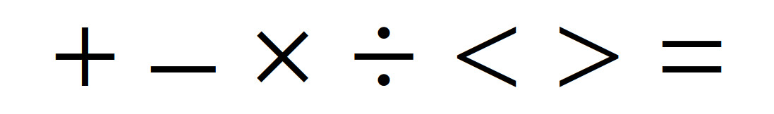
Figure 1 : maths / relational functions
Negate
Addition
Accumulate
Subtraction
Multiplication
Divider
Less than
Greater than
Equal
Less than OR Equal to
Greater than OR Equal to
To test the new simpleCPUv1d2's instruction-set i decided to write some maths routines to go with it e.g. neg, add, sub, mul and div etc. There are a number of different ways to implement these routines, different algorithms, or passing parameters using register/memory/stack etc. The implementations i have written are used for teaching purposes, to illustrate how these maths functions could be performed on a processor, sooo they are not the fastest, the smallest, or the best, rather the focus is to make them easy to understand and use. As the full instruction-set is not implemented on the simpleCPUv1d2 processor i.e. there are a number of instructions that students can build, i limited the maths functions to core instructions i.e. ones using absolute addressing mode. Therefore, parameters and results are passed via variables in memory, as shown below:
W:
  .data 0      # input
X:
  .data 0      # input
Y:
  .data 0      # output
Z:
  .data 0      # output
CNT:
  .data 0      # bit count = 16
To start with i'm going to keep things simple and use 16bit operands, to match the processor's architecture. The plan is to then add 8bit, 32bit and fixed point support. Then i guess floating point, well maybe as time allows :).
To convert positive numbers into negative numbers and vice-versa we can use 2's complement i.e. invert the bits and add 1. To invert each bit position we could use the XOR instruction, alternatively we can use the subtract instruction, as shown in figure 2. Subtracting the value to be converted from an all 1s value will invert each bit i.e. 1-1=0 and 1-0=1. Then add 1 to the result.
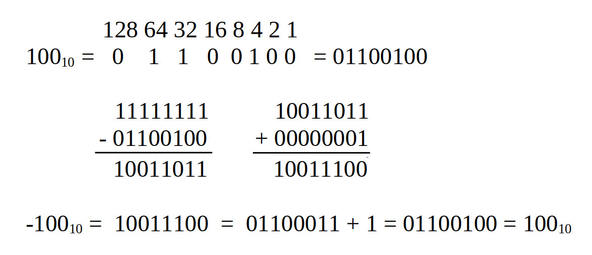
Figure 2 : 16-bit 2's complement
# negate test program

start:
  load RA DATA   # move test data into variable W
  store RA W
  call neg16

trap:
  load RA Y      # read result
  jump trap

# description: negate date Y (16bit) = -W (16bit)
# input: W (operand)
# output: Y (result)

neg16:
  move RA 0xFF   # set RA to all 1s i.e. 0xFF sign extended to 0xFFFF
  subm RA W      # subtract data to invert
  add RA 1       # increment
  store RA Y     # save result
  ret

W:
  .data 0
X:
  .data 0
Y:
  .data 0
Z:
  .data 0
CNT:
  .data 0
DATA:
  .data 100
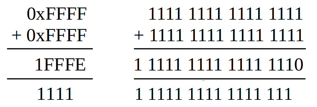
Figure 3 : 16-bit addition
A simple one, unsigned numbers, add two 16bit values to produce a 17bit result. Perhaps a little overkill to implement as a subroutine, but felt odd the leave it out. As the result could be larger than 16bits i.e. max is 0xFFFF + 0xFFFF = 0x1FFFE, we need to use two memory locations, slight overkill for 1bit, but needs to be done :). In this implementation i used the SHL instruction to move the carry flag bit into the LSB of the high result word i.e. if no carry generate shifts in a 0, if a carry is generated shifts in a 1. Note, complexity here is when we consider signed values e.g. 0xFFFF is -1 as a signed representation, so -1 + -1 = -2 which is the value 0xFFFFFFFE rather than 0x0001FFFE. Also we can generate a negaive "overflow" i.e. max_min + max_min. However, for the moment we will only consider unsigned values :).
# add test program

start:
  load RA DATA    # move test data into variable W
  store RA W
  move RA 0xFF    # set variable X to 0xFFFF
  store RA X
  call add16

trap:
  load RA Y       # read result
  load RA Z
  jump trap

# description: unsigned addition W (16bit) + X (16bit) = Y (1bit) & Z (16bit) = Total (17bit)
# input: W (operand), X (operand)
# output: Y (high result), Z (low result)

add16:
  load RA W       # read W into RA
  addm RA X       # RA = W + X
  store RA Z      # save low word result
  move RA 0       # clear RA
  shl RA          # shift left, move CY flag into LSB
  store RA Y      # save high word result
  ret

W:
  .data 0
X:
  .data 0
Y:
  .data 0
Z:
  .data 0
CNT:
  .data 0
DATA:
  .data 0xFFFF
A variation on a theme here, rather than adding two 16bit numbers together we add one 16bit number to an accumulator, a running total.
# accumulator test program

start:
  load RA DATA    # move test data into variable W
  store RA W
  call acc16

trap:
  load RA Y       # read result
  load RA Z
  jump trap

# description: unsigned addition W (16bit) + Y (16bit) Z (16bit) = Total (32bit)
# input: W (operand)
# output: Y (high result), Z (low result)

acc16:
  load RA Z       # read Z (low result) into RA
  addm RA W       # RA = Z + W
  store RA Z      # save low word result
  move RA 0       # clear RA
  shl RA          # shift left, move CY flag into LSB
  addm RA Y       # add Y (high result)
  store RA Y      # save high word result
  ret

W:
  .data 0
X:
  .data 0
Y:
  .data 0
Z:
  .data 0
CNT:
  .data 0
DATA:
  .data 0xFFFF
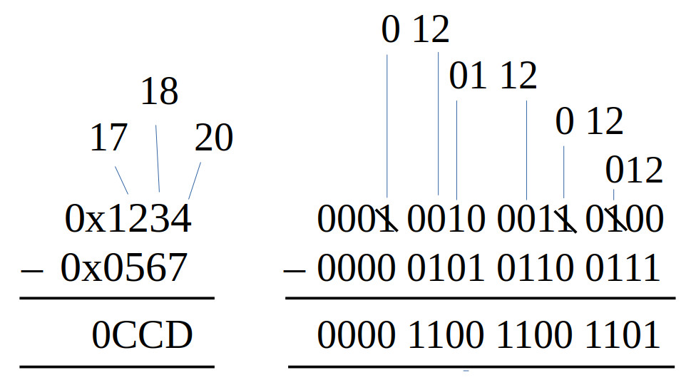
Figure 4 : 16-bit subtraction - positive result
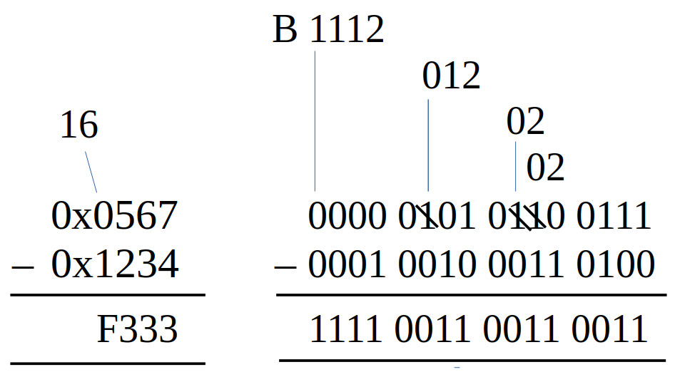
Figure 5 : 16-bit subtraction - negative result
Another simple one, unsigned numbers, subtract two 16bit values to produce a 16bit result. Again perhaps a little overkill to implement as a subroutine, but included for completeness. The joy of subtracting unsigned values is that the result will always be smaller that the original values, so no carries to worry about. However, you can generate a signed result as shown in figure 5, so you need to consider this if this result is passed to other functions e.g. multiply or divide. Note, I should add here showing how the borrows work in figures 4 and 5 was a little tricky. This is particularly difficult when looking at hexadecimal i.e. borrowing 16 rather than 2. Sooo the number above the hex digits are that columns value after the borrow, hopefully that makes sense :).
0x567  = 0000 0101 0110 0111 = 1383
0x1234 = 0001 0010 0011 0100 = 4660

0x1234 – 0x567 = 4660 – 1383 = 3277 = 0xCCD
0x567 – 0x1234 = 1383 – 4660 = −3277 = 0xF130

3277 = 0xCCD = 0000 1100 1100 1101
               1111 0011 0011 0010
-3277 =        1111 0011 0011 0011 = 0xF333
To help understand the results from the two examples, above are the two calculations and the conversion of the result -3277 into a signed binary value. As always to convert a negative value into its positive value just invert and add 1 :). Note, again the complexity here is when we come to signed arithmetic and the sign bit e.g. 0x8000 is the max_min, so 0x8000 - 0x0001 will generate a negative overflow rather than 0x7FFF, as we need more bits to represent this value, as shown in figure 6 and the conversions below. However, for the moment we will only consider unsigned values :).
07FFF   =   0000 0111 1111 1111 1111
            1111 1000 0000 0000 0000
            1111 1000 0000 0000 0001  = F8001 (incorrect, neg value)
F7FFF   =   1111 0111 1111 1111 1111
            0000 1000 0000 0000 0000
            0000 1000 0000 0000 0001  = 08001 (correct, pos value)
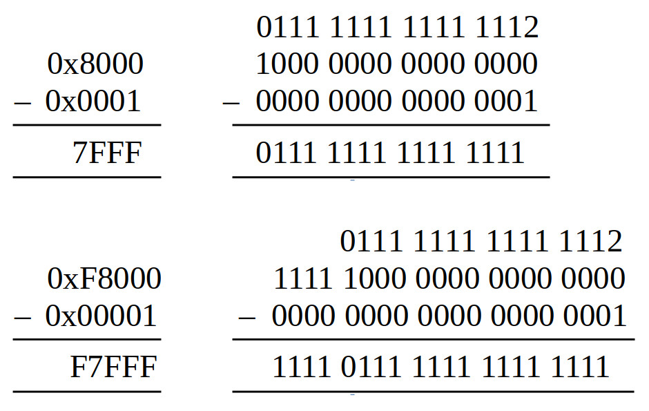
Figure 6 : 16-bit subtraction - negative overflow
# subtract test program

start:
  load RA DATA
  store RA W
  move RA 100
  store RA X
  call sub16

trap:
  load RA Y
  load RA Z
  jump trap

# description: unsigned subtraction W (16bit) - X (16bit) = Y (16bit)
# input: W (operand), X (operand)
# output: Y (result)

sub16:
  load RA W
  subm RA X
  store RA Y
  ret

W:
  .data 0
X:
  .data 0
Y:
  .data 0
Z:
  .data 0
CNT:
  .data 0

DATA:
  .data 0x7FF
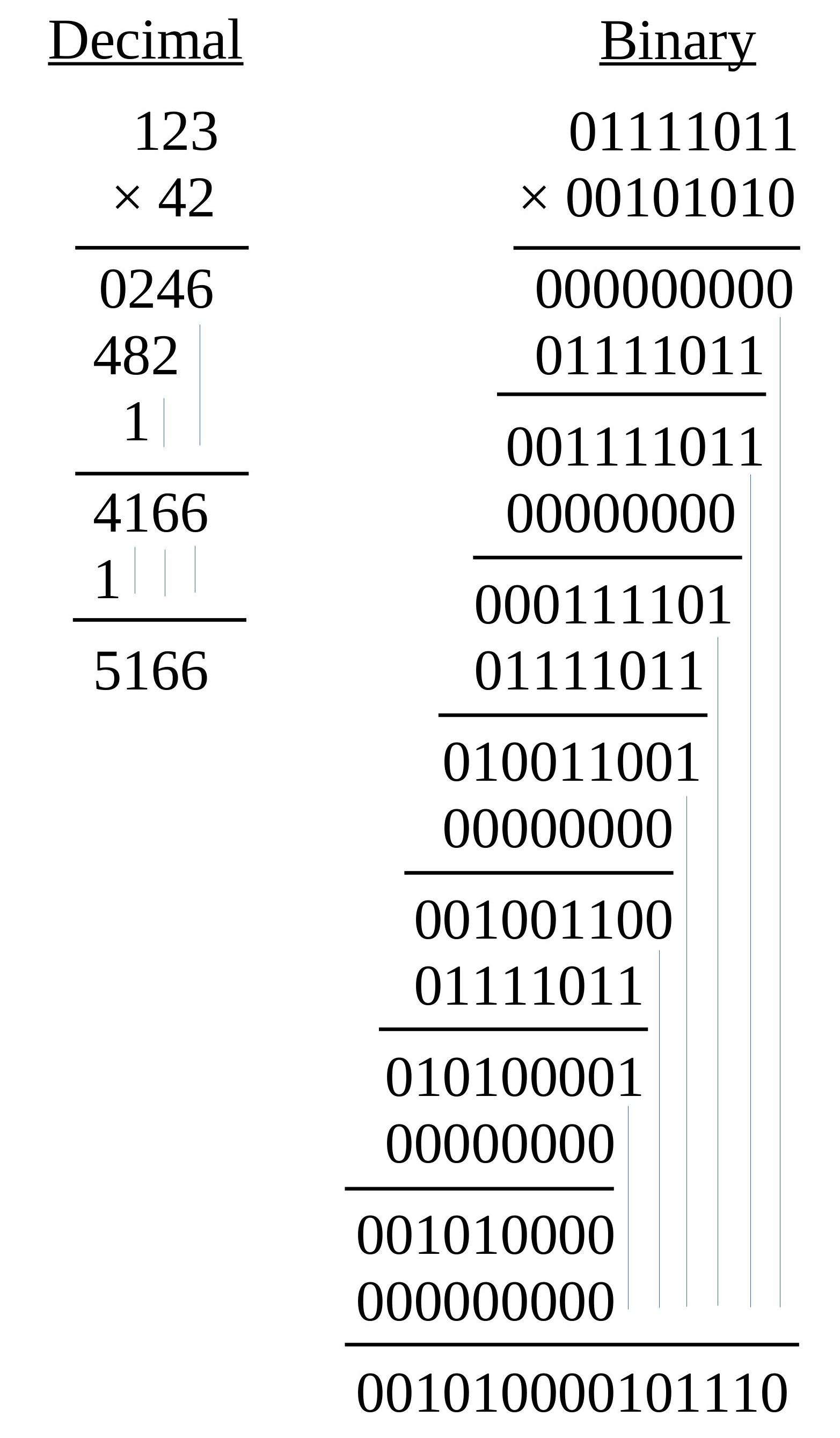
Figure 7 : multiply
The nice thing about base-2 multiplication is that when you perform long multiplication you don't have to do any multiplication :). When you work through each multiplier when it is a 0 you write out 0s and when its a 1 you write out the multiplicand i.e. you are calculating multiplicand x 0 or multiplicand x 1. Then these values are added together to produce the partial product, as shown in figure 7.
In software this is the first function not directly supported by the processor i.e. there is no MUL instruction, therefore we need to design/select a multiplication algorithm (Link). There are a few different approaches to select from, but i'm going to keep it simple and go for the classic shift and add approach. The operation of this algorithm is described by the flowchart in figure 8.
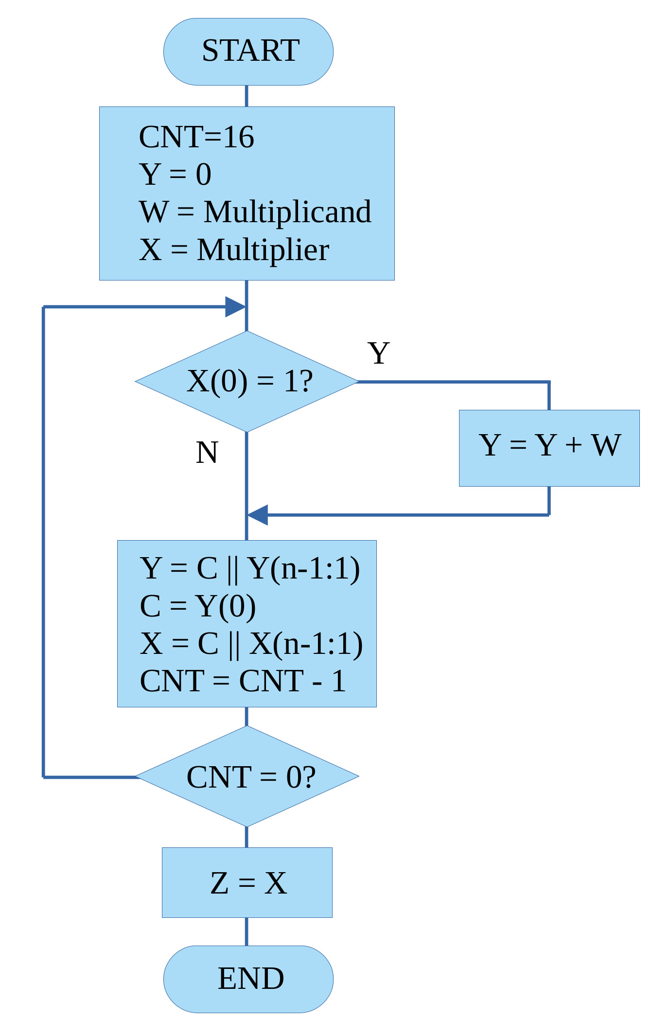
Figure 8 : multiply
This algorithm follows the basic steps of binary multiplication described in figure 7. However, rather than the partial product "growing" to the left, in the software implementation we shift the partial product to the right i.e. so that addition step is always performed on the same bit positions, or to put it another way, the LSB of each partial product is not used in future calculations, so shifting this bit to the right, out of the working register is a useful thing to do :). Therefore, a key thing to identify here is that the multiplier variable X is overwritten by the result, as when performing this algorithm we only need to examine the multiplier's LSB. Note, key thing to remember is that the Y=Y+W step could generate a 17bit result, sooo the carry flag (C) needs to also be shifted when the right shift is performed as this is the 17th result bit. This is automatically done when we use the SHR instruction. We do not need to test if an overflow was generated as the carry flag will be set accordingly after the add i.e. no carry C=0, carry C=1.
# multiply test program

start:
  load RA DATA
  store RA W
  move RA 100
  store RA X
  call mul16

trap:
  load RA Y
  load RA Z
  jump trap

# description: unsigned multiplication W (16bit) x X (16bit) = Y (16bit) & Z (16bit) = Total (32bit)
# input: W (multiplicand), X (multiplier)
# output: Y (high result), Z (low result)

mul16:
  move RA 0
  store RA Y
  move RA 16
  store RA CNT        # Loop counter = 16 bits

mul_loop:
  load RA X
  and RA 1            # Test LSB of multiplier
  jumpz mul_no_add    # If LSB = 0, skip add

  load RA Y           # add multiplicand to partial product
  addm RA W
  store RA Y

mul_no_add:
  load RA Y           # shift partial product
  shr RA
  store RA Y

  load RA X
  shr RA              # Shift multiplier right by 1 (next bit)
  store RA X

  load RA CNT
  sub RA 1            # Decrement counter
  store RA CNT
  jumpnz mul_loop     # Repeat if bits remain

  load RA X
  store RA Z
  ret

W:
  .data 0
X:
  .data 0
Y:
  .data 0
Z:
  .data 0
CNT:
  .data 0

DATA:
  .data 0x7FF
Figure 9 : division - no remainder
Figure 10 : division - remainder
Again another function not directly supported by the processor's hardware. Like multiplication there are a lot of different algorithms to chose from (Link), but i'm going to keep it simple and go again for the classic shift and subtract approach i.e. the restoring division algorithm (Link). The operation of this algorithm is described by the flowchart in figure 11.
Figure 11 : division flowchart
This algorithm repeatedly tests to see if the divisor can be subtracted from the section of the dividend being processed. If it can, that bit position in the quotient is set to 1, otherwise its set to 0. The term restoring is use to describe what happens in the event that the divisor can not be subtracted i.e. the divisor is bigger than section of the dividend, so a negative result is produces at the end of the subtraction phase. When performing division manually this is just ignored, but when implemented in software we need to undo this subtraction step, sooo to restore the part of the dividend being processed we add back the divisor. To illustrate this process consider the steps shown below performing 100 divided by 5:
   100     00000000 00000000 00000000 01100100 = Dividend = YZ
     5     00000000 00000000 00000000 00000101 = Divisor  = X

STEP  OPERATION       Y                 Z
1     shift   00000000 00000000 00000000 11001000
2     shift   00000000 00000000 00000001 10010000
3     shift   00000000 00000000 00000011 00100000
4     shift   00000000 00000000 00000110 01000000
5     shift   00000000 00000000 00001100 10000000
6     shift   00000000 00000000 00011001 00000000
7     shift   00000000 00000000 00110010 00000000
8     shift   00000000 00000000 01100100 00000000
9     shift   00000000 00000000 11001000 00000000
10    shift   00000000 00000001 10010000 00000000
11    shift   00000000 00000011 00100000 00000000
12    shift   00000000 00000110 01000000 00000000
      sub 5   00000000 00000101 01000000 00000000
      result  00000000 00000001 01000000 00000001
13    shift   00000000 00000010 10000000 00000010
14    shift   00000000 00000101 00000000 00000100
      sub 5   00000000 00000101 00000000 00000100
      result  00000000 00000000 00000000 00000101
15    shift   00000000 00000000 00000000 00001010
16    shift   00000000 00000000 00000000 00010100
Note, the restore phase is not show to save space e.g. in steps 1 to 11 where the Y register contains a value less than 101. In these cases subtracting 5 would generate a negative result. When this is detected 5 is added to Y to undo the previous subtraction, then the YZ memory is shifted to the left 1bit position, adding a new digit.
This division algorithm produces a quotient and a remainder i.e. integer results, it does not produce a fractional representation. To represent a fractional term we would need to move to a fixed point representation as shown in figure 12. Here we have a 16bit integer part and an 8bit fractional part. Therefore, there may be resolution issues i.e. can you represent the fractional term given the fixed number of fractional bits :(.
Figure 12 : fixed point division
# divide test program

start:
  load RA DATA
  store RA W
  move RA 100
  store RA X
  call div16

trap:
  load RA Y
  load RA Z
  jump trap

# description: unsigned division W (16bit) / X (16bit) = Y (16bit) Quotient, Z (16bit) Remainder
# input: W (Dividend), X (Divisor)
# output: Y (Quotient), Z (Remainder)

div16:
  load RA W
  store RA Z
  move RA 0
  store RA Y
  move RA 16
  store RA CNT

div_loop:
  load RA Z
  asl RA
  store RA Z

  load RA Y
  shl RA
  store RA Y

  load RA Y
  subm RA X
  store RA Y
  jumpn div_restore

  load RA Z
  add RA 1
  store RA Z
  jump div_update

div_restore:
  load RA Y
  addm RA X
  store RA Y

div_update:
  load RA CNT
  sub RA 1
  store RA CNT
  jumpnz div_loop

  ret

W:
  .data 0
X:
  .data 0
Y:
  .data 0
Z:
  .data 0
CNT:
  .data 0

DATA:
  .data 0xFFFF
Relational test, is W less-than X, if true store 1 in Y, if false store 0 in Y.
# less-than test program

start:
  load RA DATA
  store RA W
  move RA 100
  store RA X
  call lt16

trap:
  load RA Y
  jump trap

# description: unsigned relational test, is W less-than X
# input: W (operand), X (operand)
# output: Y (result), 0=False, 1-True

lt16:
  load RA W
  subm RA X
  jumpn lt_true

lt_false:
  move RA 0
  store RA Y
  ret

lt_true:
  move RA 1
  store RA Y
  ret

W:
  .data 0
X:
  .data 0
Y:
  .data 0
Z:
  .data 0
CNT:
  .data 0

DATA:
  .data 0xFFFF
Relational test, is W greater-than X, if true store 1 in Y, if false store 0 in Y.
# greater-than test program

start:
  load RA DATA
  store RA W
  move RA 100
  store RA X
  call gt16

trap:
  load RA Y
  jump trap

# description: unsigned relational test, is W greater-than X
# input: W (operand), X (operand)
# output: Y (result), 0=False, 1-True

gt16:
  load RA W
  subm RA X
  jumpz gt_false
  jumpp gt_true

gt_false:
  move RA 0
  store RA Y
  ret

gt_true:
  move RA 1
  store RA Y
  ret

W:
  .data 0
X:
  .data 0
Y:
  .data 0
Z:
  .data 0
CNT:
  .data 0

DATA:
  .data 0xFFFF
Relational test, is W equal-to X, if true store 1 in Y, if false store 0 in Y.
# equal-to test program

start:
  load RA DATA
  store RA W
  move RA 100
  store RA X
  call eq16

trap:
  load RA Y
  jump trap

# description: unsigned relational test, is W equal-to X
# input: W (operand), X (operand)
# output: Y (result), 0=False, 1-True

eq16:
  load RA W
  subm RA X
  jumpz eq_true

eq_false:
  move RA 0
  store RA Y
  ret

eq_true:
  move RA 1
  store RA Y
  ret

W:
  .data 0
X:
  .data 0
Y:
  .data 0
Z:
  .data 0
CNT:
  .data 0

DATA:
  .data 0xFFFF
Relational test, is W less-than-equal-to X, if true store 1 in Y, if false store 0 in Y.
# less-than-equal-to test program

start:
  load RA DATA
  store RA W
  move RA 100
  store RA X
  call lte16

trap:
  load RA Y
  jump trap

# description: unsigned relational test, is W less-than-equal-to X
# input: W (operand), X (operand)
# output: Y (result), 0=False, 1-True

lte16:
  load RA W
  subm RA X
  jumpz lte_true
  jumpn lte_true

lte_false:
  move RA 0
  store RA Y
  ret

lte_true:
  move RA 1
  store RA Y
  ret

W:
  .data 0
X:
  .data 0
Y:
  .data 0
Z:
  .data 0
CNT:
  .data 0

DATA:
  .data 0xFFFF
Relational test, is W greater-than-equal-to X, if true store 1 in Y, if false store 0 in Y.
# greater-than-equal-to test program

start:
  load RA DATA
  store RA W
  move RA 100
  store RA X
  call gte16

trap:
  load RA Y
  jump trap

# description: unsigned relational test, is W greater-than-equal-to X
# input: W (operand), X (operand)
# output: Y (result), 0=False, 1-True

gte16:
  load RA W
  subm RA X
  jumpn gte_false

gte_true:
  move RA 1
  store RA Y
  ret

gte_false:
  move RA 0
  store RA Y
  ret

W:
  .data 0
X:
  .data 0
Y:
  .data 0
Z:
  .data 0
CNT:
  .data 0

DATA:
  .data 0xFFFF
WORK IN PROGRESS

This work is licensed under a Creative Commons Attribution-NonCommercial-NoDerivatives 4.0 International License.
Contact email: mike@simplecpudesign.com