Babbage designed a series of mechanical 'computers' based upon the humble cog: a wheel or bar with a series of projections on its edge, which transfer motion by engaging with projections on another wheel or bar (Oxford Concise Dictionary).
At first glance these machines seem to be historical artefacts, dinosaurs of the computing world. However, if you were to look more closely you can find all the major architectural elements found in any modern computer. These machines are much more than their simple cogs, cams and levers. Technologies may change, but by considering the design decisions made in their construction a better understanding of what a computer is and what it does can be obtained.
In some respects computers have not changed that much since Babbage's times, an instruction is still an instruction. The flavours of instruction used has changed over time, but a modern designer still faces the same questions Babbage did: how should information be represented and how can it be efficiently processed. Reading and research can give insight into these problems, but the best way to understand a problem is by doing. Therefore, to explore these questions (and to have a play with the 3D printer) I'm going to make a smaller version of Babbage's first mechanical 'computer' i.e. Difference Engine 0.5.
The aim of this work is to complete a demonstrator model to support first year teaching of computer architectures.
At the end of this project I hope to release the full source 'code' for this machine so that other people with the same desire to inhale far to many toxic gas fumes from their 3D printer can produce their own, or better Difference engines. However, at the moment my design is very much a work in progress, therefore, to avoid flooding the world with fundamentally flawed prototypes I'm limiting access to a few photos / pictures.
Software - 3D models are defined using OpenScad, initial virtual prototype implemented in Blender. Constructed all of the main components, gears mesh nicely. A few problems with the 3D printer, the bottom layer not forming correctly. Another problem is shrinkage of the plastic (ABS) as it cools, reducing the size of the centre hole, also adding significant levels of backlash in the gears. Not sure how to over come this, apart from trial and error.
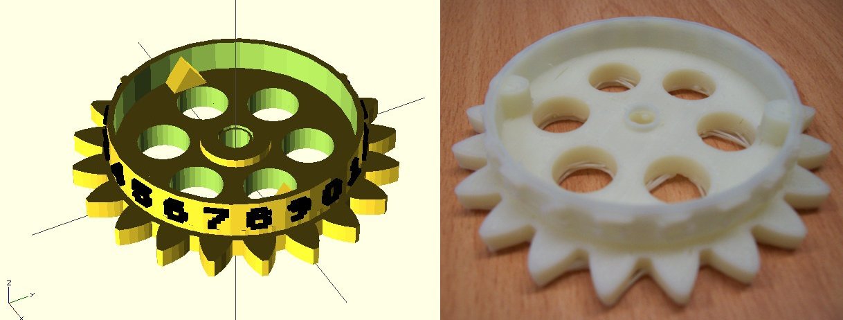
Figure 1.0 : Figure Wheel: stores one decimal digit
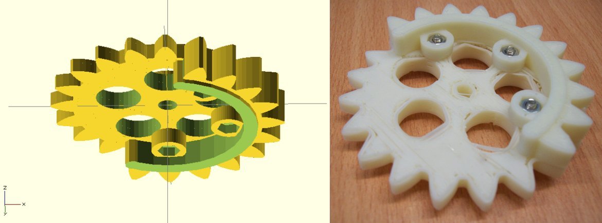
Figure 1.1 : Sector Wheel: data communication signal
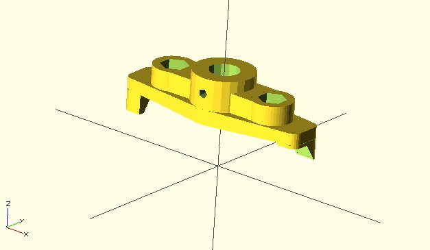
Figure 1.2 : Drive Arm: control signal
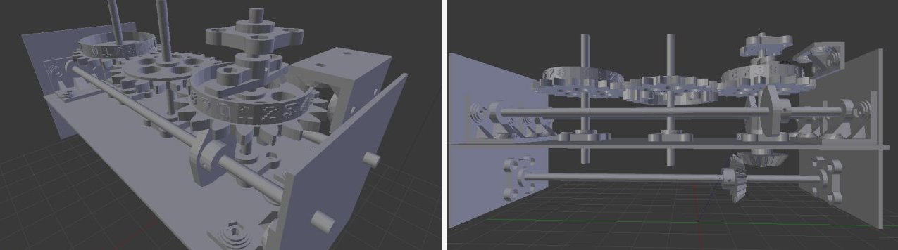
Figure 1.3 : Top and side view of first prototype
3D printer seems a lot better, a recalibration and a few parameters changed. First test: to see if the lower half gear would disengage during the restore cycle. Looks OK, however, spotted a small mistake, printed the numbers on one cog in the wrong order i.e. should have been descending and not ascending
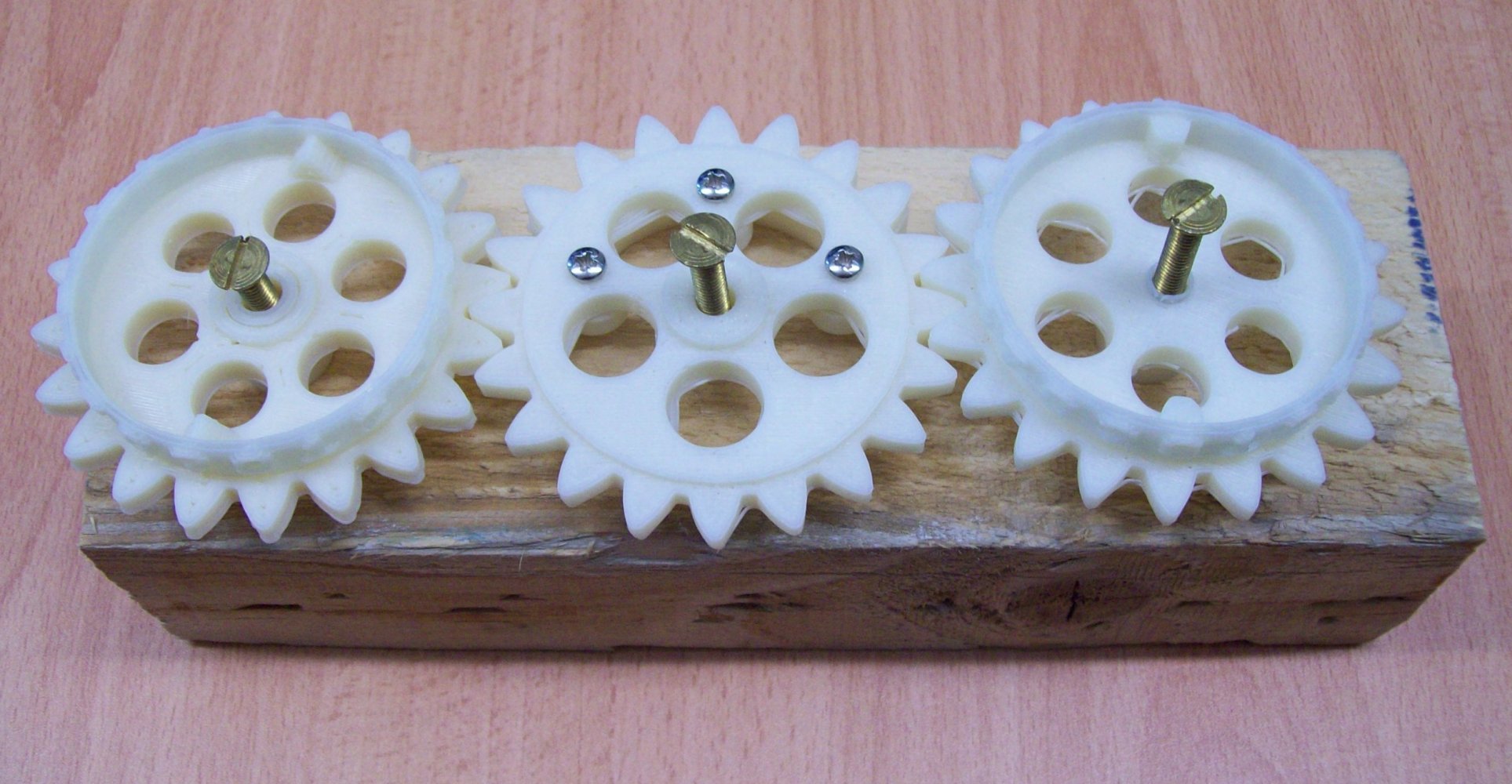
Figure 1.4 : Top and side view of prototype 1
Printed out bearing blocks, look OK, but have some gaps in the printing i.e. a floating bearing, not really what you want. Not a big problem will reduce the number of shells to 3 and fill with glue. Always wondered why Babbage's figure wheels had 40 teeth, perhaps one factor is in the restore phase, using only 20 teeth means the gears must be inline to prevent the lower half of the restore gear from engaging with the accumulating figure gear. Having 40 teeth would mean you only use 1/4 of the gear, therefore you can offset the restore gear making the machine more compact. Also quicker, only need to turn a 1/4 of a revolution?
Got distracted with other work (building an automatic bug trap), but have finished off the rest of the printing. Since I have reduced the number of shells to 3 all of the component look OK. However, owing to the heated bed the first layer has spread out a little (or could be incorrect calibration). Not normally a problem, but this means that the drive surface on each cog is very narrow i.e. the first layer, could file, but I think I will see how it goes.
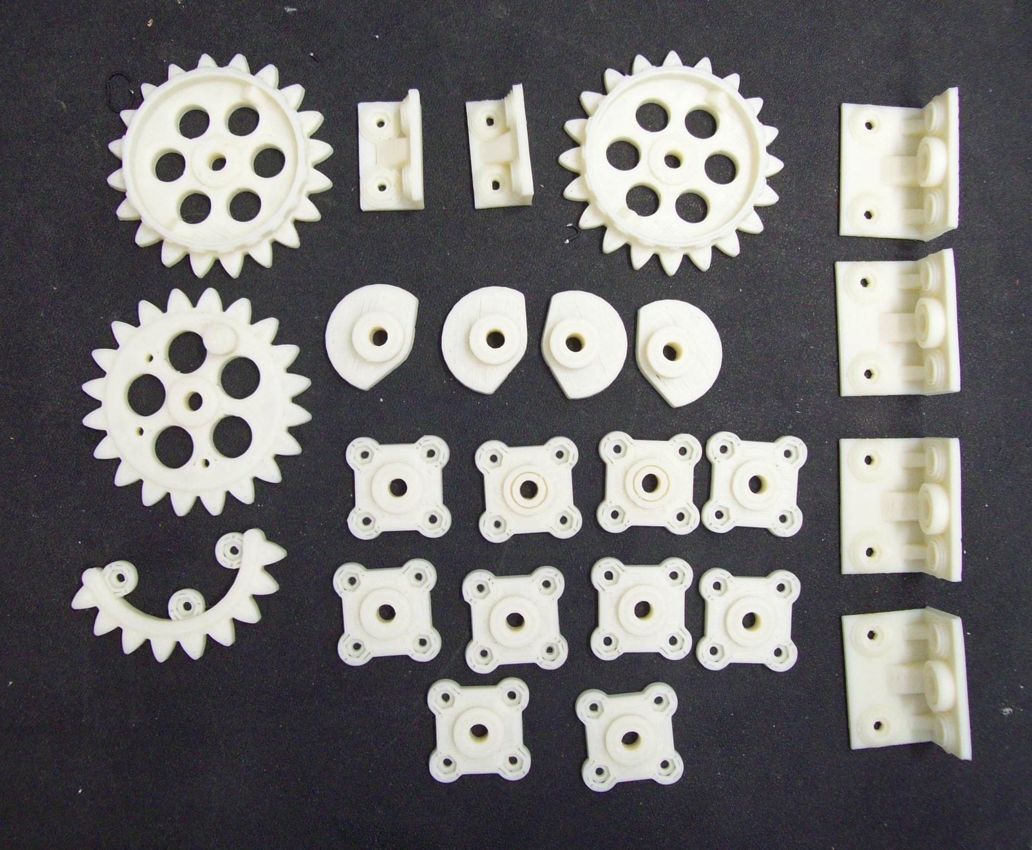
Figure 1.5 : A selection of parts (some missing)
Assembled the parts, did need to file/scrape off the misformed first layer to allow the cogs to rotate freely. Note, don't try to ream bearings on aluminium base as this removes too much plastic, need to do them separately and then align. This initial prototype works OK, only one small mistake, the figure wheel drive arm needs to be redesigned as it doesn't quiet align when adding 0. Also one design decision that may need to be reconsidered is the restore phase. To reduce the mechanical complexity of the drive chain the restore phase requires the lower drive shaft to be reversed i.e. it is rotated one turn clockwise to perform the addition, then rotate one turn anticlockwise to perform the restore. This will add an extra layer of complexity for the control cogs (these still need to be designed).
Video of 4+2 - FourPlusTwo.avi, FourPlusTwo.mp4.
Video of 1+9 - OnePlusNine.avi, OnePlusNine.mp4.
Video of 6+0 - SixPlusZero.avi, SixPlusZero.mp4.
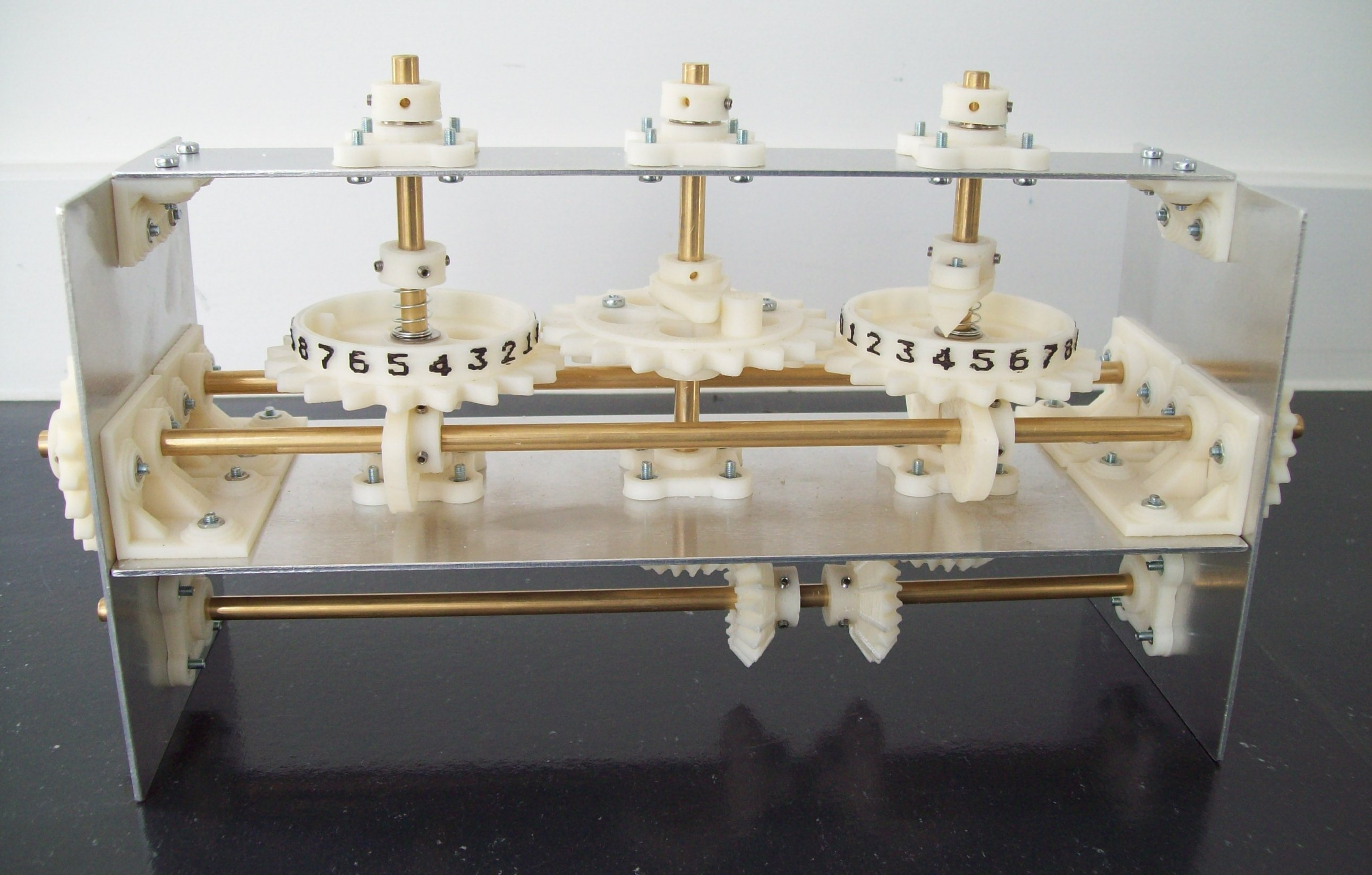
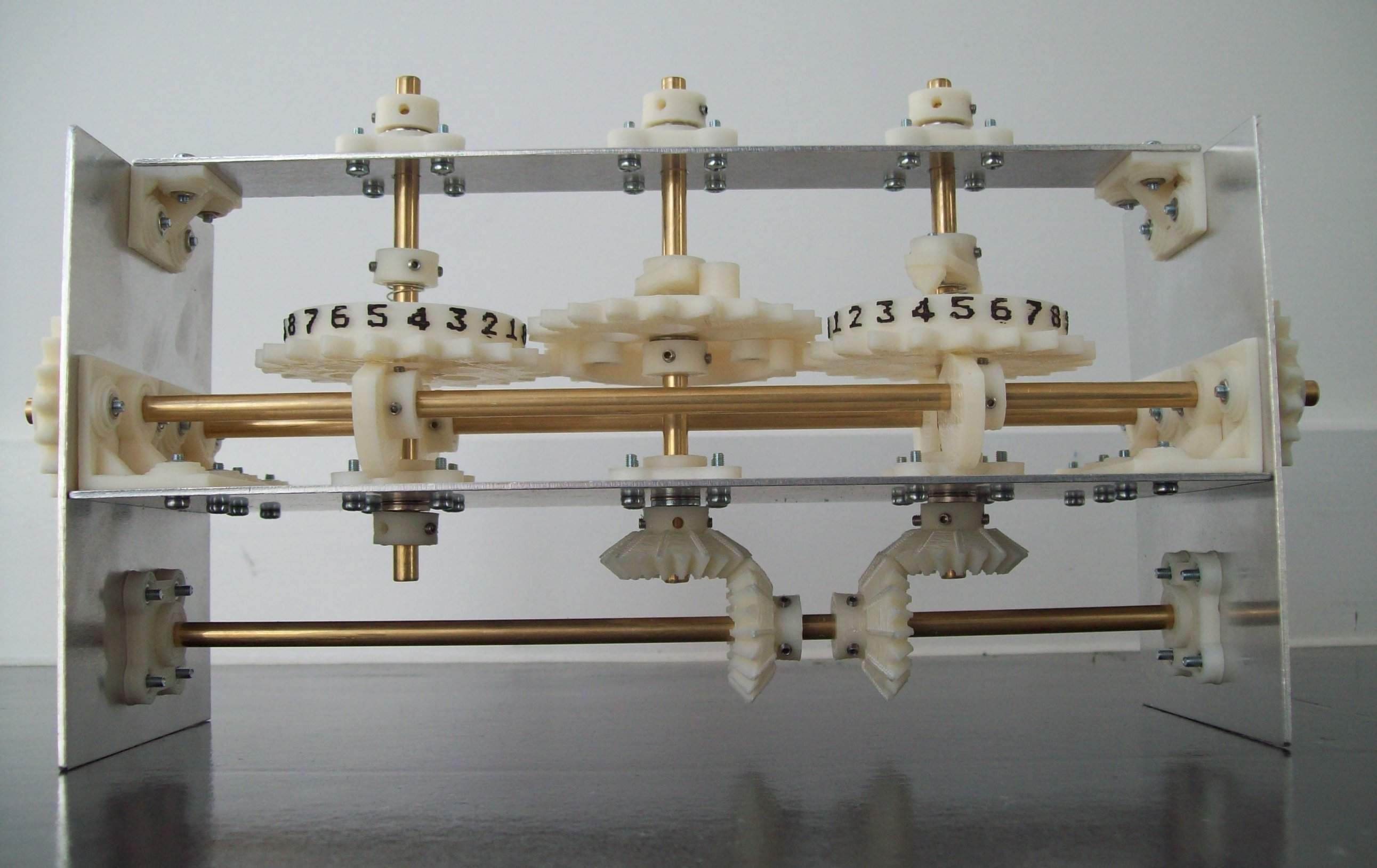
Figure 1.6 : Front view of prototype 2
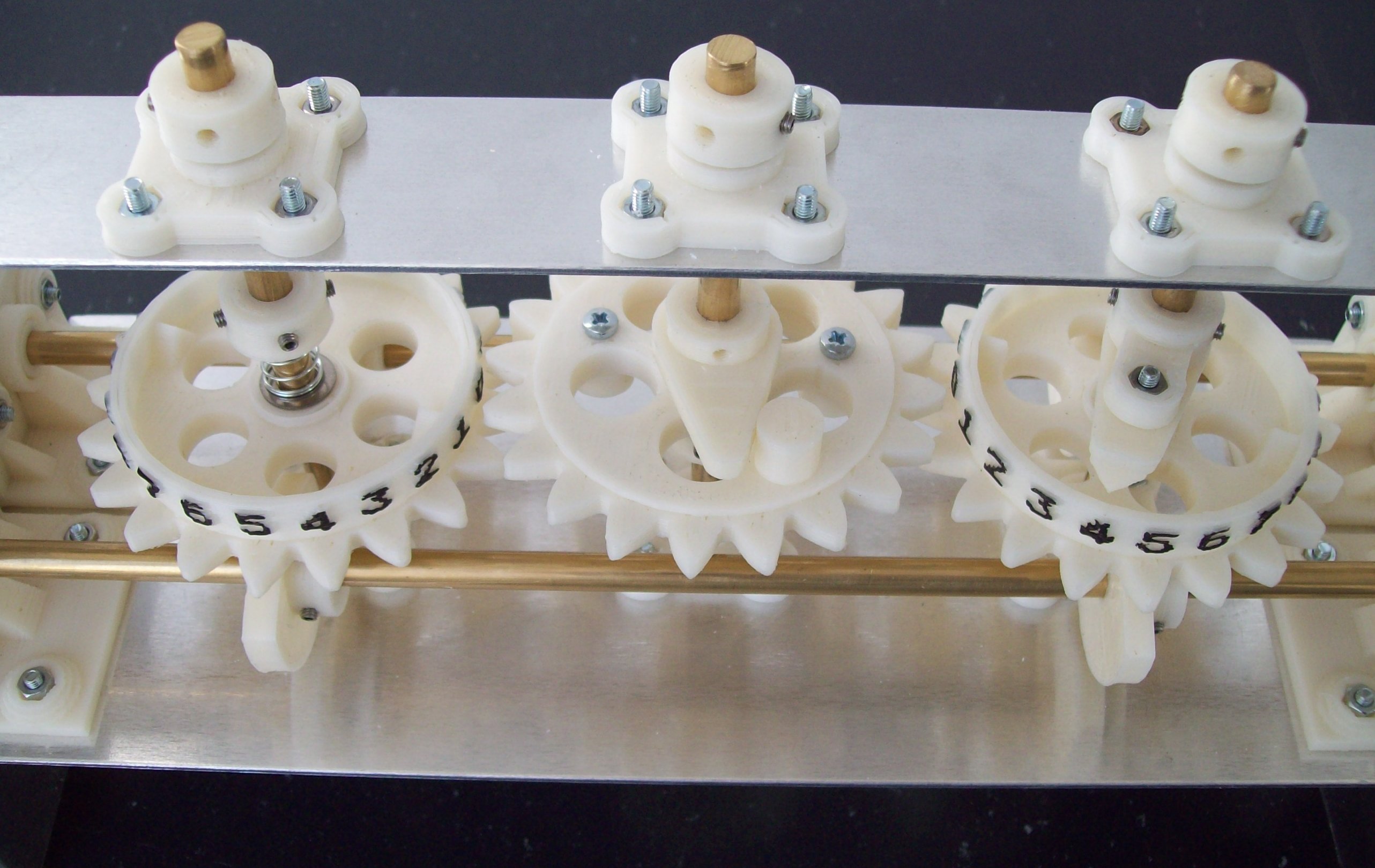
Figure 1.7 : Top view of prototype 2
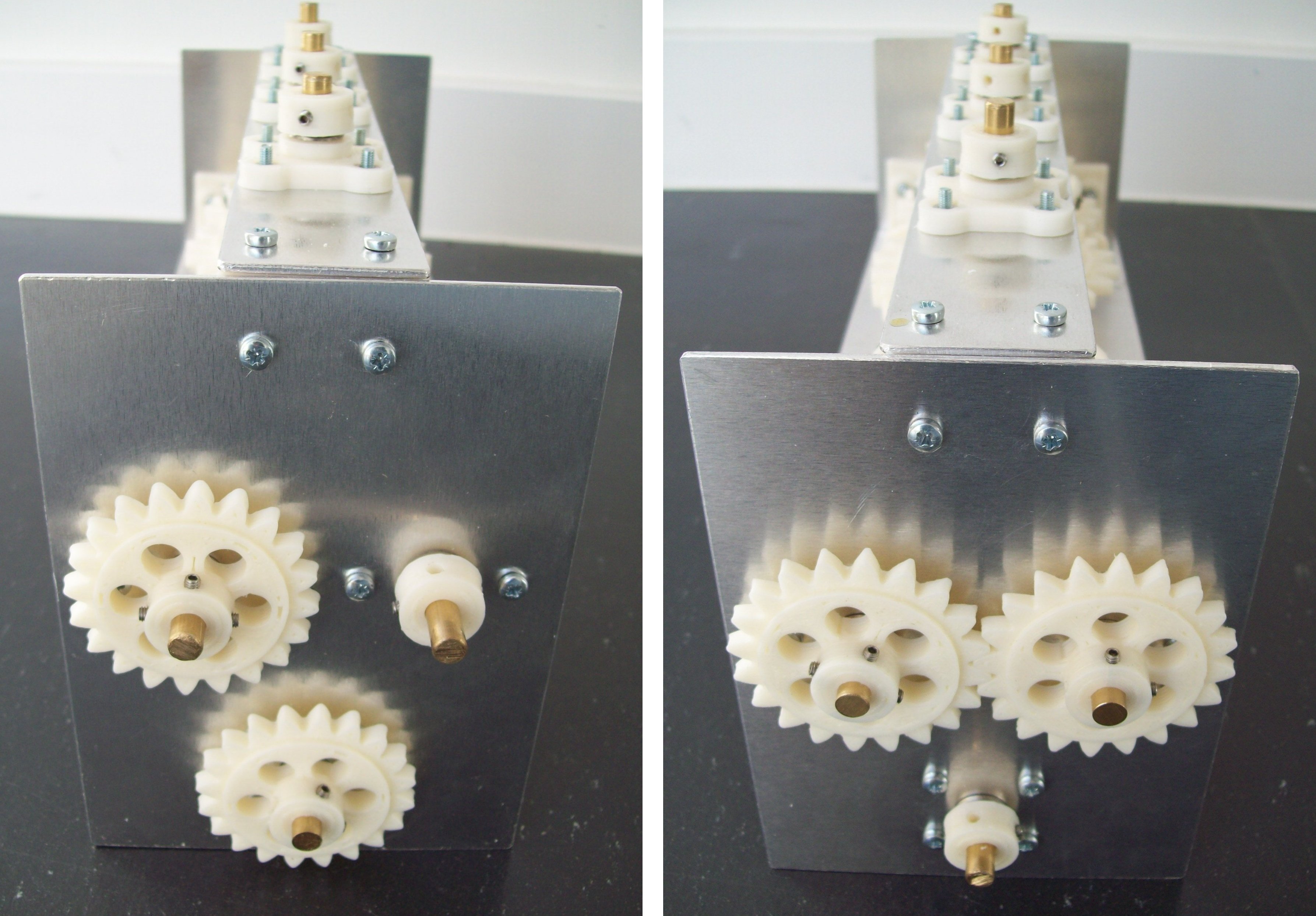
Figure 1.8 : End view of prototype 2, left - missing control cogs, right - cam drive
Not quite finished, wanted to sort out the gears so that you could turn a handle and the machine would repeatedly add / accumulate i.e. count. Problem is that the control gearbox would be a bit of a pain to make. Therefore, taking a pause, may come back to it, but for now the OpenSCAD files are in the zip below. Sorry, just a big pile of files. If anyone takes this further please do email me a picture
Zip of OpenSCAD files DifferenceEngineOpenSCAD.zip.
An example lab script based on the original Difference Engine is available here:

This work is licensed under a Creative Commons Attribution-NonCommercial-NoDerivatives 4.0 International License.
Contact email: mike@simplecpudesign.com