A summary of documents taken from SimpleCPU lectures, practicals and web pages, please refer back to these for more detailed information / explanation: (Link).
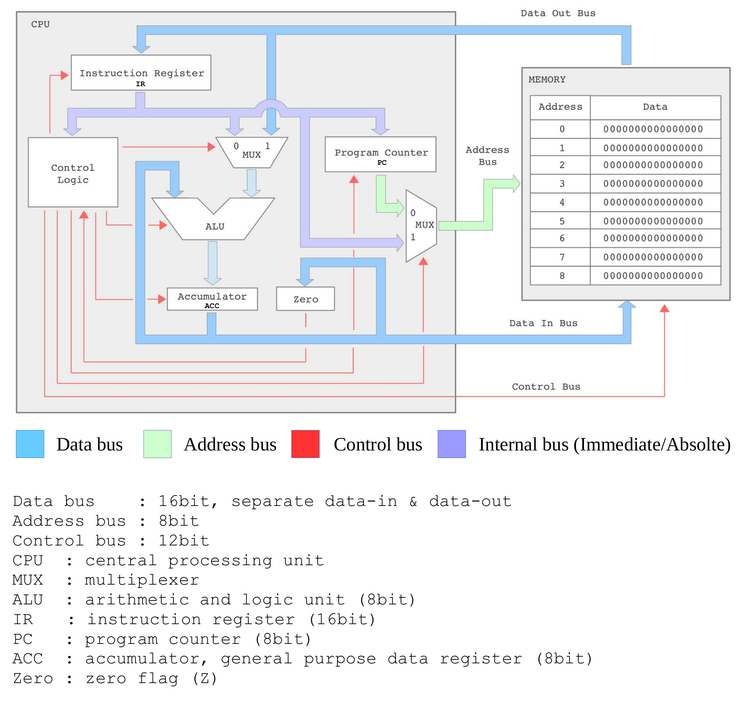
Figure 1 : SimpleCPU_v1a block diagram
This processor uses a fixed length 16bit instruction format. Memory is 256 x 16bit, allowing an instruction to be stored in a single memory location. On reset the first instruction is fetched from address 0. The data processing unit i.e. ALU is 8bit wide. To simplify the hardware implementation data values are only read / written to the lower 8bits of each memory location, the higher 8bits is not used i.e. this processor does not support byte addressable memory.
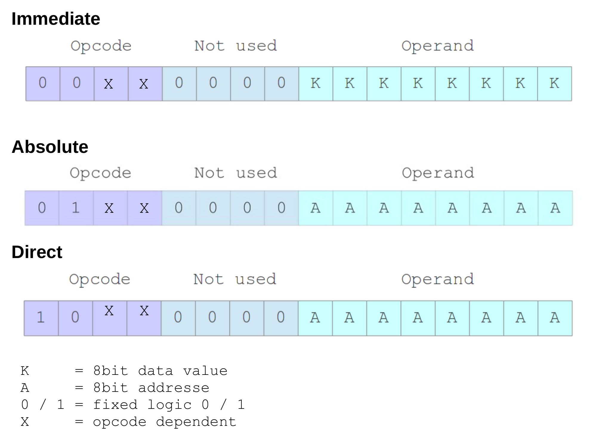
Figure 2 : SimpleCPU_v1a addressing modes
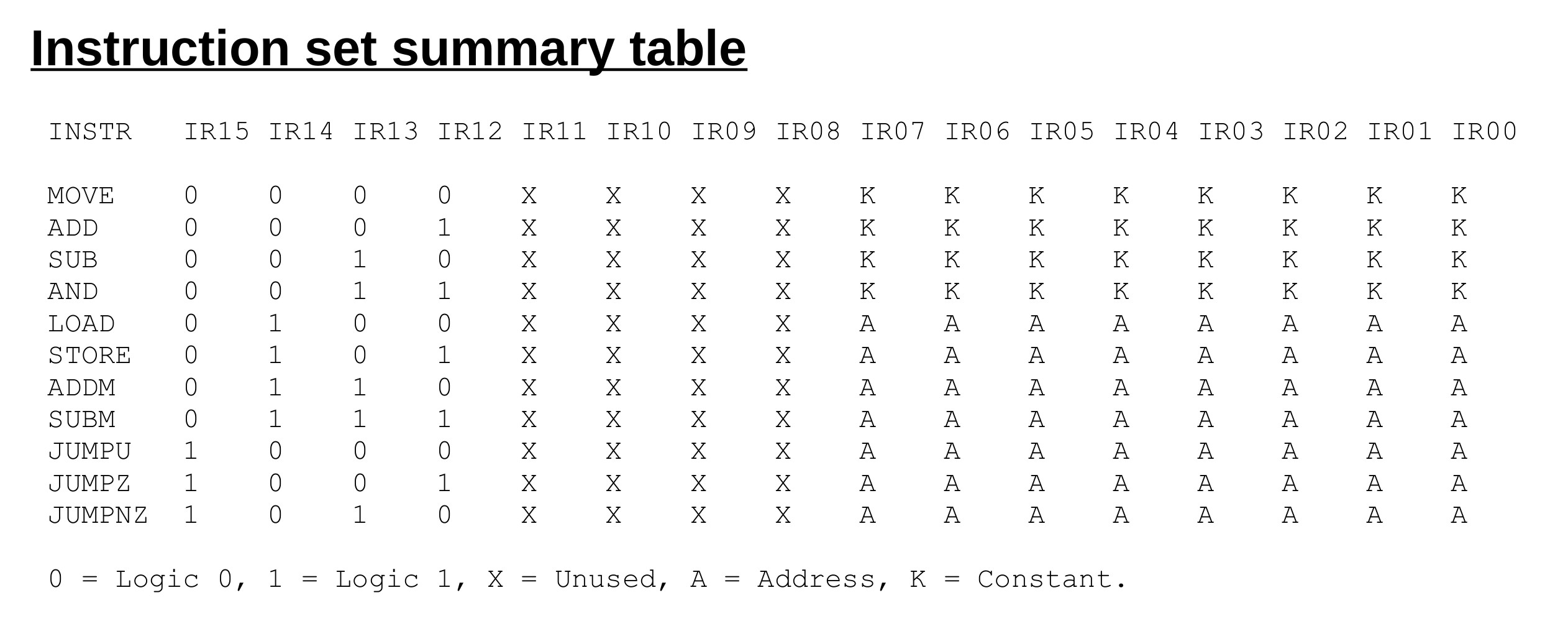
Figure 3 : SimpleCPU_v1a instruction-set
Example         :  move 1
Addressing mode :  immediate
Opcode          :  0000
RTL             :  ACC <- KK
Flags set       :  Z
Move 8bit value into the accumulator (ACC). The bit field KK is as defined in figure 2. In this example KK is the value 1, therefore, at the end of the execution phase the ACC=1 and Z=0. Note, the Z flag is determined by the value stored in the ACC i.e. if ACC=0, then Z=1.
Example         :  add 2
Addressing mode :  immediate
Opcode          :  0001
RTL             :  ACC <- ACC + KK
Flags set       :  Z
Add 8bit value to the accumulator (ACC). The bit field KK is as defined in figure 2. In this example KK is the value 2, therefore, if ACC=1 at the end of the execution phase the ACC=3 and Z=0. Note, this CPU does not implement a carry flag. The Z flag is determined by the value stored in the ACC i.e. if ACC=0, then Z=1.
Example         :  sub 3
Addressing mode :  immediate
Opcode          :  0010
RTL             :  ACC <- ACC - KK
Flags set       :  Z
Subtract signed 8bit value from the accumulator (ACC). The bit field KK is as defined in figure 2. In this example KK is the value 3, therefore, if ACC=3 at the end of the execution phase the ACC=0 and Z=1. Note, this CPU does not implement a carry flag. The Z flag is determined by the value stored in the ACC i.e. if ACC=0, then Z=1.
Example         :  and 4
Addressing mode :  immediate
Opcode          :  0011
RTL             :  ACC <- ACC & KK
Flags set       :  Z
Perform bitwise AND on the accumulator (ACC). The bit field KK is as defined in figure 2. In this example KK is the value 4, therefore, if ACC=7 at the end of the execution phase the ACC=4. Note, the Z flag is determined by the value stored in the ACC i.e. if ACC=0, then Z=1.
Example         :  load 123
Addressing mode :  absolute
Opcode          :  0100
RTL             :  ACC <- M[AA]
Flags set       :  Z
Transfer an 8bit value from memory to the accumulator (ACC) i.e. the lower byte of the 16bit value stored in the selected memory location. Note, high byte not used. The bit field AA is as defined in figure 2. In this example AA is address 123, therefore, if M[123]=9 at the end of the execution phase the ACC=9. Note, the Z flag is determined by the value stored in the ACC i.e. if ACC=0, then Z=1.
Example         :  store 124
Addressing mode :  absolute
Opcode          :  0101
RTL             :  M[AA] <- ACC
Flags set       :  None
Store accumulator (ACC) value to memory i.e. ACC written to lower byte of the 16bit value stored in the selected memory location. Note, high byte hard-wired, default 0. The bit field AA is as defined in figure 2. In this example AA is address 124, therefore, if ACC=8 at the end of the execution phase the M[124]=8.
Example         :  addm 125
Addressing mode :  absolute
Opcode          :  0110
RTL             :  ACC <- ACC + M[AA]
Flags set       :  Z
Add 8bit value stored in memory to accumulator (ACC) i.e. the lower byte of the 16bit value stored in the selected memory location. Note, high byte not used. The bit field AA is as defined in figure 2. In this example the AA is address 125, therefore, if ACC=2 and M[125]=1 at the end of the execution phase the ACC=3. Note, this CPU does not implement a carry flag. The Z flag is determined by the value stored in the ACC i.e. if ACC=0, then Z=1.
Example         :  subm 126
Addressing mode :  absolute
Opcode          :  0111
RTL             :  RA <- RA - M[AA]
Flags set       :  Z
Subtract 8bit value stored in memory from accumulator (ACC) i.e. the lower byte of the 16bit value stored in the selected memory location. Note, high byte not used. The bit field AA is as defined in figure 2. In this example AA is the address 126, therefore, if ACC=2 and M[126]=1 at the end of the execution phase the ACC=1. Note, this CPU does not implement a carry flag. The Z flag is determined by the value stored in the ACC i.e. if ACC=0, then Z=1.
Example         :  jump 200
Addressing mode :  direct
Opcode          :  1000
RTL             :  PC <- AA
Flags set       :  None
Unconditional jump. The bit field AA is as defined in figure 2. In this example the branch target address AA is 200, at the end of the execution phase the PC will be updated with the value 200.
Example         :  jumpz 201
Addressing mode :  direct
Opcode          :  1001
RTL             :  IF Z=1 THEN PC <- AA ELSE PC <- PC + 1
Flags set       :  None
Jump if accumulator (ACC) is zero. The bit field AA is as defined in figure 2. In this example the branch target address AA is 201, therefore, if Z=1 at the end of the execution phase the PC will be updated with the value 201, else PC updated with PC+1.
Example         :  jumpnz 202
Addressing mode :  direct
Opcode          :  1010
RTL             :  IF Z=0 THEN PC <- AA ELSE PC <- PC + 1
Flags set       :  None
Jump if accumulator (ACC) is not zero. The bit field AA is as defined in figure 2. In this example the branch target address AA is 202, therefore, if Z=0 at the end of the execution phase the PC will be updated with the value 202, else PC updated with PC+1.
Pseudo Code             Assembler code              Notes
A = 0                   start:                      variables A, B, C and D are stored
B = 10                      move 0                  in memory. Values limited to 8bit.
C = D                       store A                 Variables may also be initialised
                            move 10                 using the .data assembler
                            store B                 directive
                            load C
                            store D
                        trap:
                            jump trap
                        A:
                            .data 0
                        B:
                            .data 0
                        C:
                            .data 123
                        D:
                            .data 0
Note, values larger than 8bits must be stored over multiple memory locations. These data types are not supported by the processor i.e. can not be directly processed, therefore, suitable software must be used, examples given in workshops.
Pseudo Code             Assembler code              Notes
IF A=0                    start:                      variables A and B stored in
THEN                        load A                    memory. Zero flag (z) is directly
    B = 10                  jumpz zero                  driven from ACC.
ELSE                    notZero:
    B = 20                  move 20
END IF                      jump skip
                        zero:
                            move 10
                        skip:
                            store B
                        trap:
                            jump trap
                        A:
                            .data 0
                        B:
                            .data 0
Note, if possible always try and construct a test were the variable is 0 as this simplifies coding i.e. conditional jumps are based on the Z flag.
Pseudo Code            Assembler code                Notes
IF A=B                  start:                         variables A, B and C stored in
THEN                        load A                      memory. Zero flag (z) directly
    C = C + 1               subm B                      driven from ACC. If result of
END IF                      jumpnz trap                 subtraction is zero then A=B
                        equal:
                            load C
                            add 1
                            store C
                        trap:
                            jump trap
                        A:
                            .data 0
                        B:
                            .data 0
                        C:
                            .data 0
Pseudo Code            Assembler code                Notes
IF A(2)=1              start:                          variables A and B stored in
THEN                        load A                     memory. Test if bit 2 of variable
    B = B x 2               and 4                      A is set to 1.
END IF                      jumpz trap
                        one:
                            load B                     Multiplication implemented using
                            addm B                     repeated addition
                            store B
                        trap:
                            jump trap
                        A:
                            .data 0
                        B:
                            .data 0
Pseudo Code            Assembler code                Notes
FOR I in {0..4}        start:                          variables I and A stored in
DO                          move 4                     memory.
    A = A + 1               store I
DONE                    loop:
                            load I
                            sub 1
                            store I
                            jumpz exit
                            load A
                            add 1
                            store A
                            jump loop
                        exit:
                            jump exit
                        A:
                            .data 0
                        I:
                            .data 0
Pseudo Code            Assembler code                Notes
A = B / 2                start:                        division implemented using
                            move 0                     repeated subtraction. Value of
                            store A                    B limited to 0 - 127
                            load B
                            store TMP
                        loop:                          while loop
                            load TMP
                            sub 2
                            store TMP
                            and 0x80
                            jumpnz exit
                            load A
                            add 1
                            store A
                            jump loop
                        exit:
                            jump exit
                        A:
                            .data 0
                        B:
                            .data 0
                        TMP:
                            .data 0
Note, repeated subtraction is not the best method in terms of processing performance, but it is simple to code and small :)
Pseudo Code            Assembler code                Notes
A = B * 2               start:                        repeated addition
                            load B
                            addm B
                            store B
                        exit:
                            jump exit
                        A:
                            .data 0
                        B:
                            .data 0
Pseudo Code            Assembler code                Notes
A = B * 10               start:
                            load B
                            addm B
                            store C                    B x 2
                            store A
                            addm C                     B x 4
                            store C
                            addm C                     B x 8
                            addm A                     B x 10
                            store A

                        exit:
                            jump exit
                        A:
                            .data 0
                        B:
                            .data 0
                        C:
                            .data 0
Note, for x10 code size not significantly smaller than for simple repeated addition, however, in general this approach does result in better code density for larger values.

This work is licensed under a Creative Commons Attribution-NonCommercial-NoDerivatives 4.0 International License.
Contact email: mike@simplecpudesign.com